Rotary Keyboard

Background
I have a coworker who is fond of reminiscing about the good ol’ days, when his grandparents had a rotary dial phone on the wall that they were renting from the phone company. Combine this with his devotion to the tenkey pad on a full-size keyboard and the fact that I happened to have an old rotary dial in my bin of spare parts, and the path forward for this year’s April Fool’s prank was self-evident.
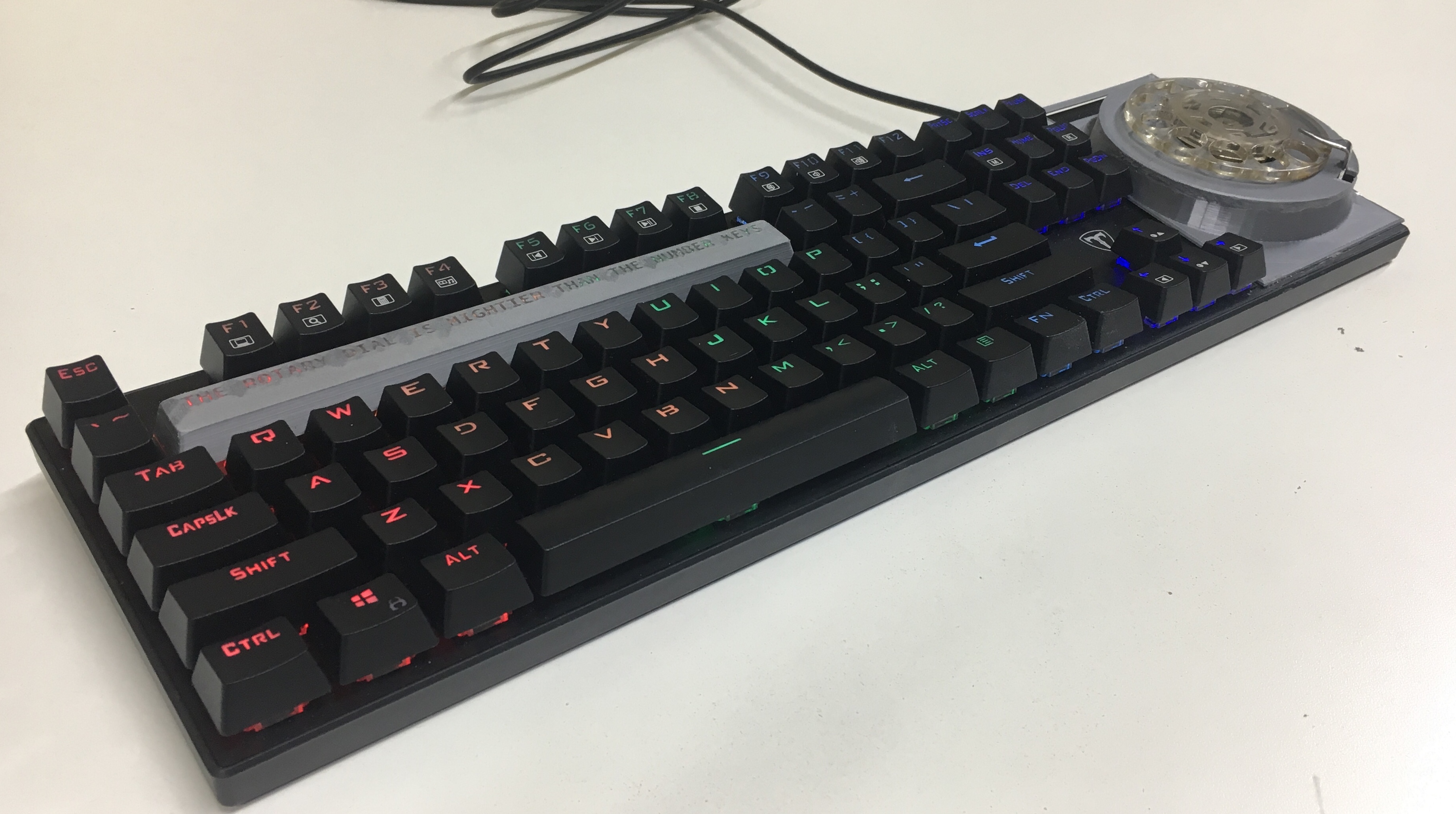
I mean, of course, that buying a cheap $13 mechanical keyboard off eBay and hacking the rotary dial into it was the most reasonable course of action.
Firmware
While the easy route out with a fabrication project like this is just to go for cosmetic completeness, I figured that it was imperative that the dial actually work for numeric input - especially since I was planning to remove the number row as well, thus forcing the use of the rotary dial for numeric or symbolic entry.
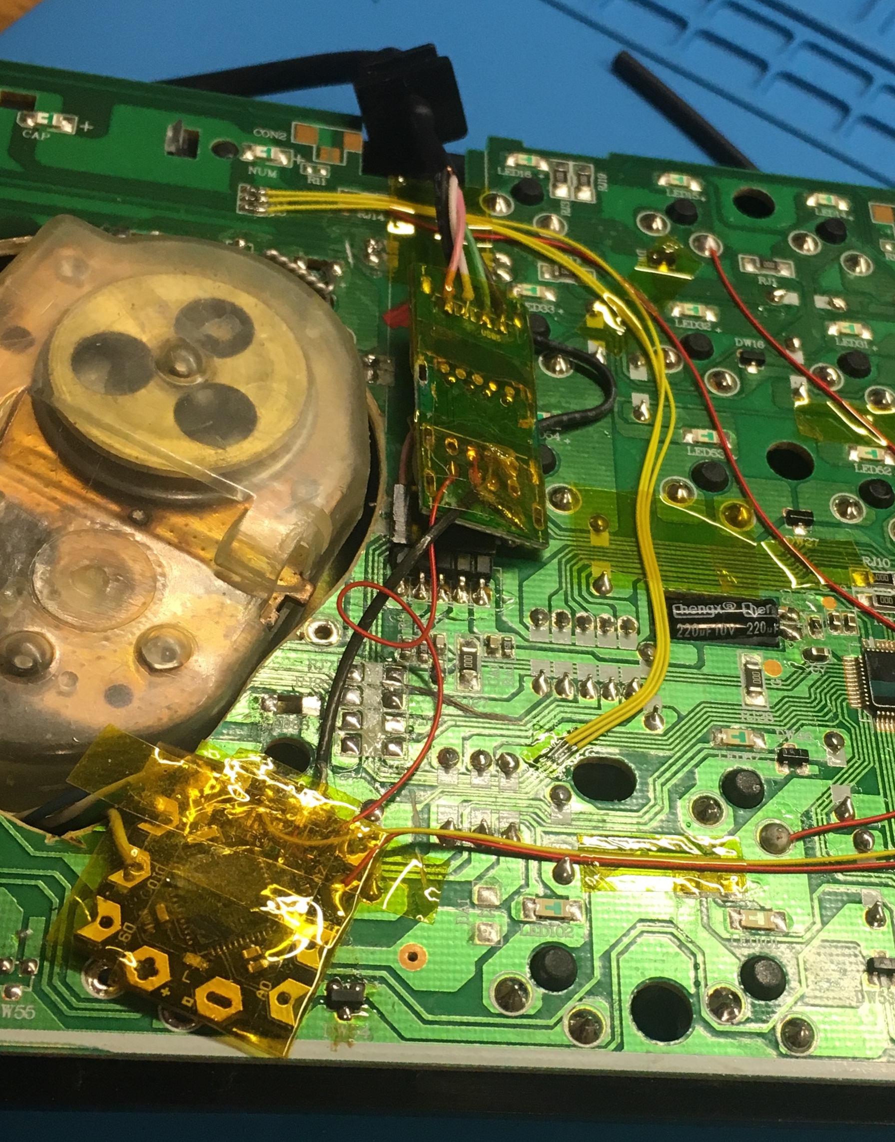
My rotary dial has two primary pairs of contacts. One goes open when the dial is moved past the 1 position, and the other creates the characteristic pulse train upon release (one pulse per numeric position). While one could use a pin-change interrupt, the timescale is so large that busy-waiting is acceptable. I used a DFRobot Beetle for this since its onboard ATMega32u4 provides native USB HID functionality.
while (digitalRead(ACTIVE)) // Active-low
{
  int count = 0;

  while (!digitalRead(ACTIVE))
  {
    if (digitalRead(PULSE))
    {
      count += 1;
      delay(50);
    }
  }
  if (count >= 2)
  {
    count /= 2;
    count = (count == 10) ? 0 : count;
    Keyboard.print(count);
  }
}
Due to debouncing troubles, it seems to be double-reading each pulse. At some point I should throw a scope on it to confirm what the problem is, but it works quite adequately as-is. (My first try only had a 10ms delay, which empirically resulted in septuple-reading each pulse…)
Electrical
To power this keyboard, it seems like I would need two cables, one for the Arduino and one for the original keyboard controller. However, this is somewhat awkward. The topology that made the most sense to me was to shoehorn a USB hub into the keyboard, soldering both the Arduino and the keyboard controller to the hub’s device inputs.
This allowed me to solder the keyboard’s built-in USB port to the hub’s upstream connection. Thus, when I plug the physical keyboard into a computer, I am plugging in a USB hub that allows both devices to connect while preserving the illusion of a single-cable USB device.
The cheapest hub I could find with a useful form-factor was this wacky three-port beast.
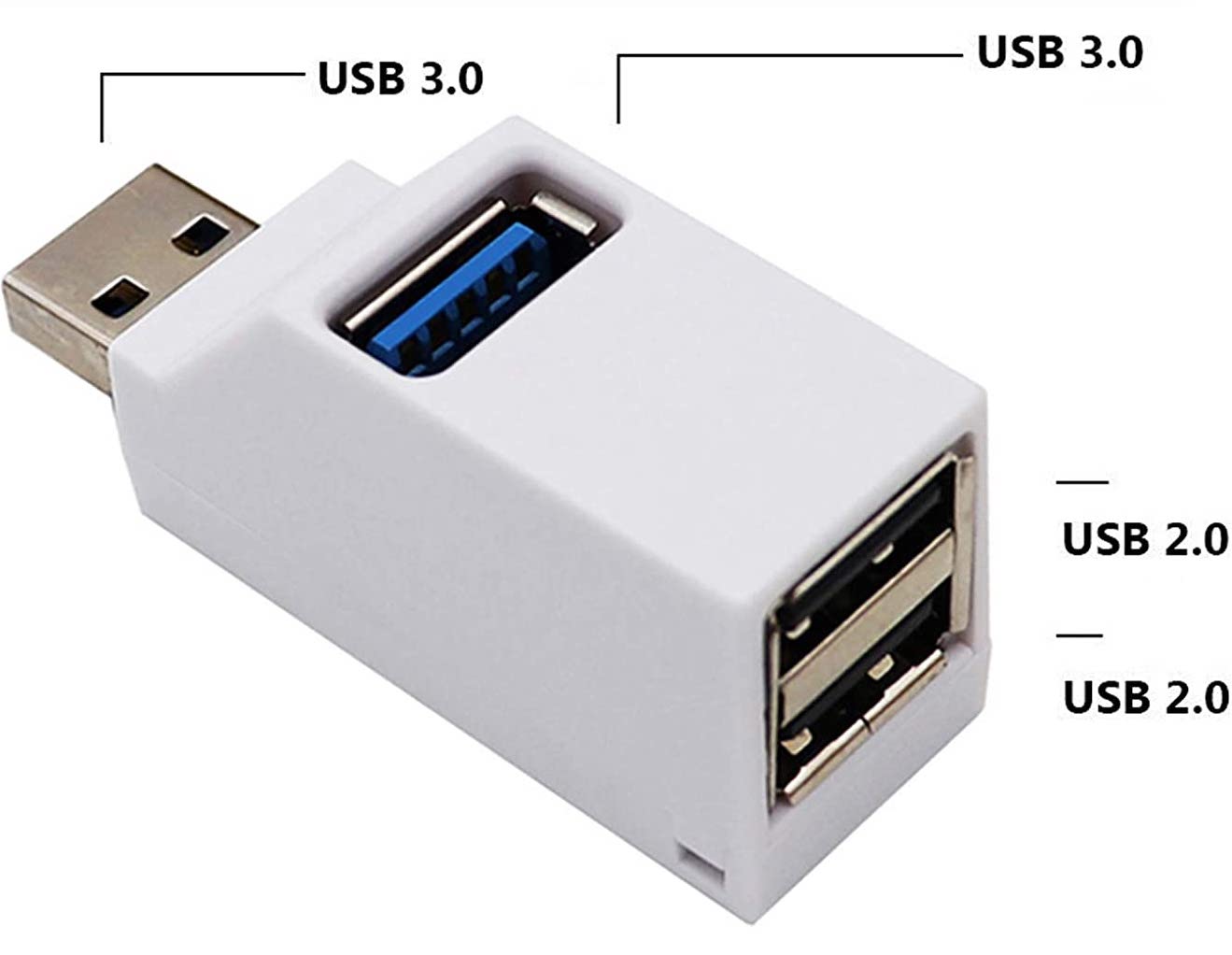
As an interesting aside, the top-firing port on this hub is indeed SuperSpeed-compatible: the SSRX+/- and SSTX+/- pairs are an entirely independent interface from the D+/- pair used for Full-Speed or High-Speed USB and so can be routed directly to the port without an intermediate hub.
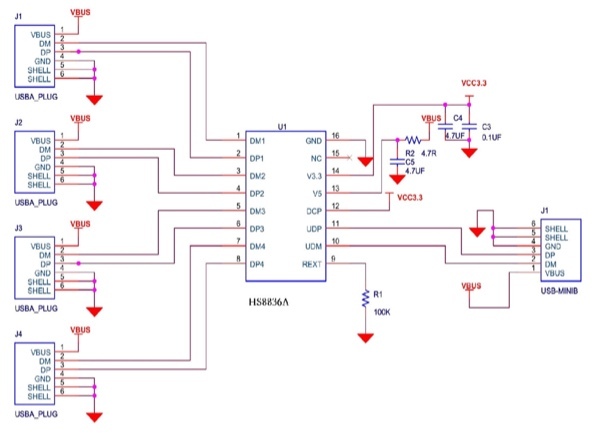
The chip doing all the heavy lifting in this hub is the monolithic HS8836A, which is supposedly rated for High-Speed USB traffic and has an impressively low count of support components.
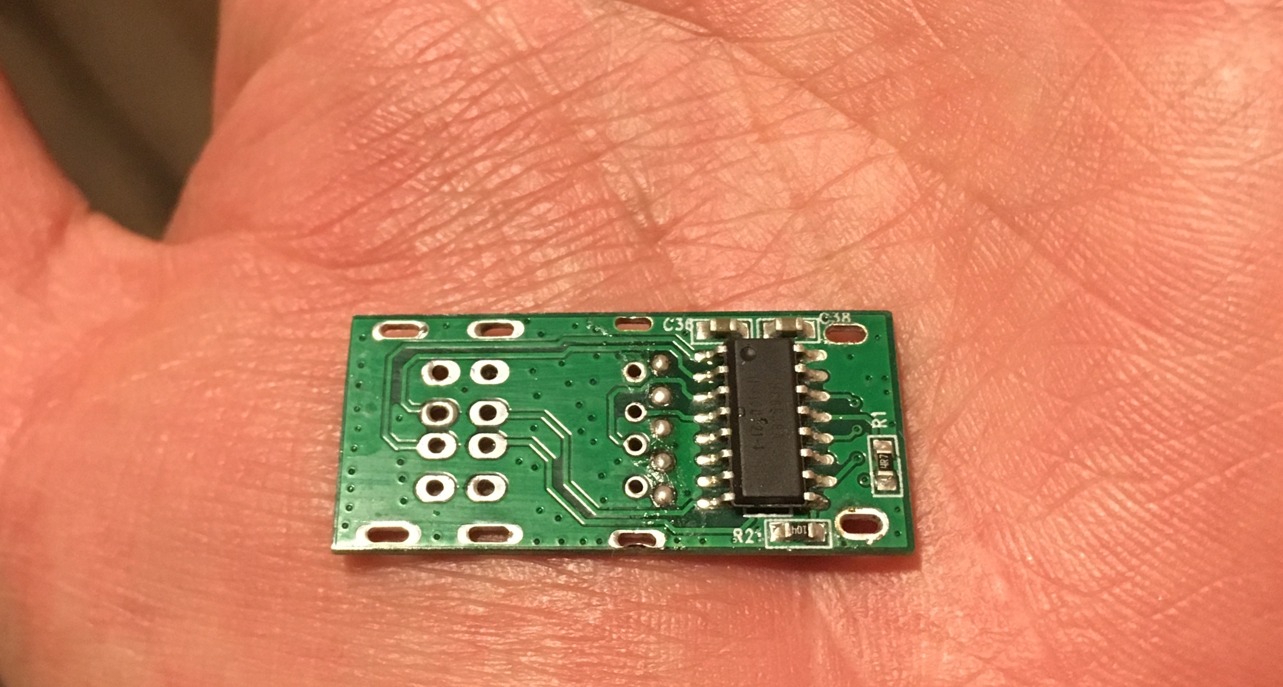
In my case, I just had to desolder the existing ports in a clean enough fashion to avoid melting the hub IC (I definitely did not melt the first one I ordered) and wire in the USB signals from the keyboard and Arduino. Note how compact this board is thanks to the HS8836A:
I used some shielded differential lines from an iMac’s LVDS display harness for the data connections to the Arduino because they were sitting in my junk pile and didn’t run away quickly enough. I suspect the impedance is totally off, but USB 1.1 is remarkably robust.
Keyboard
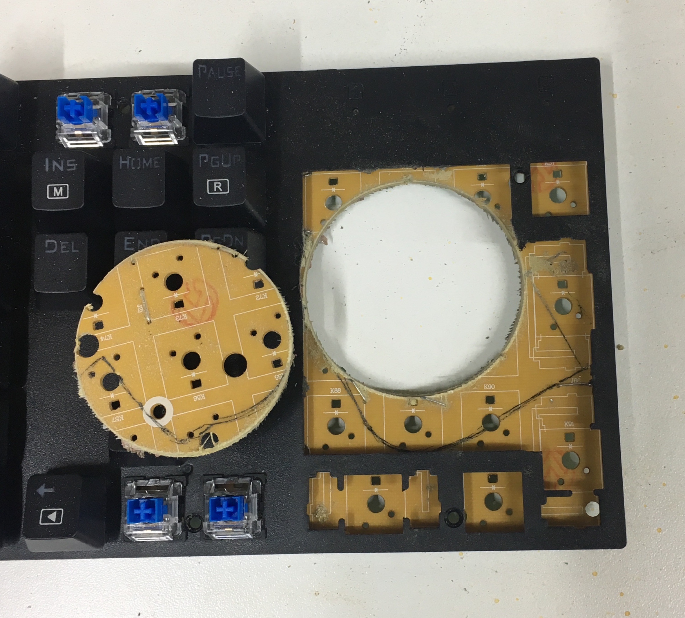
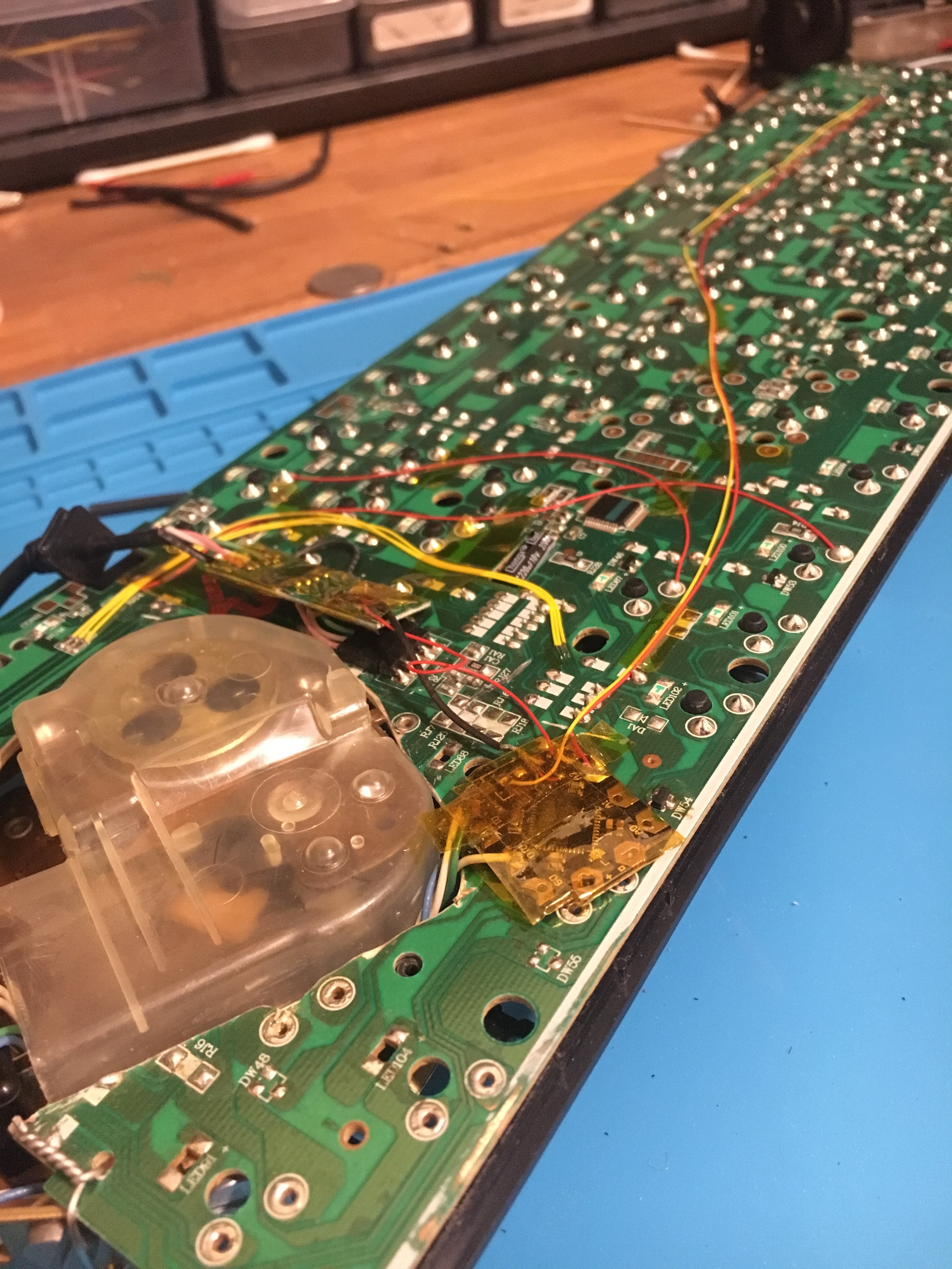
In order to replace the tenkey with the rotary dial, I had to remove the all of the switches for the number pad, which was relatively easy due to the fact that this keyboard has a single-sided PCB and my solder sucker is well-behaved.
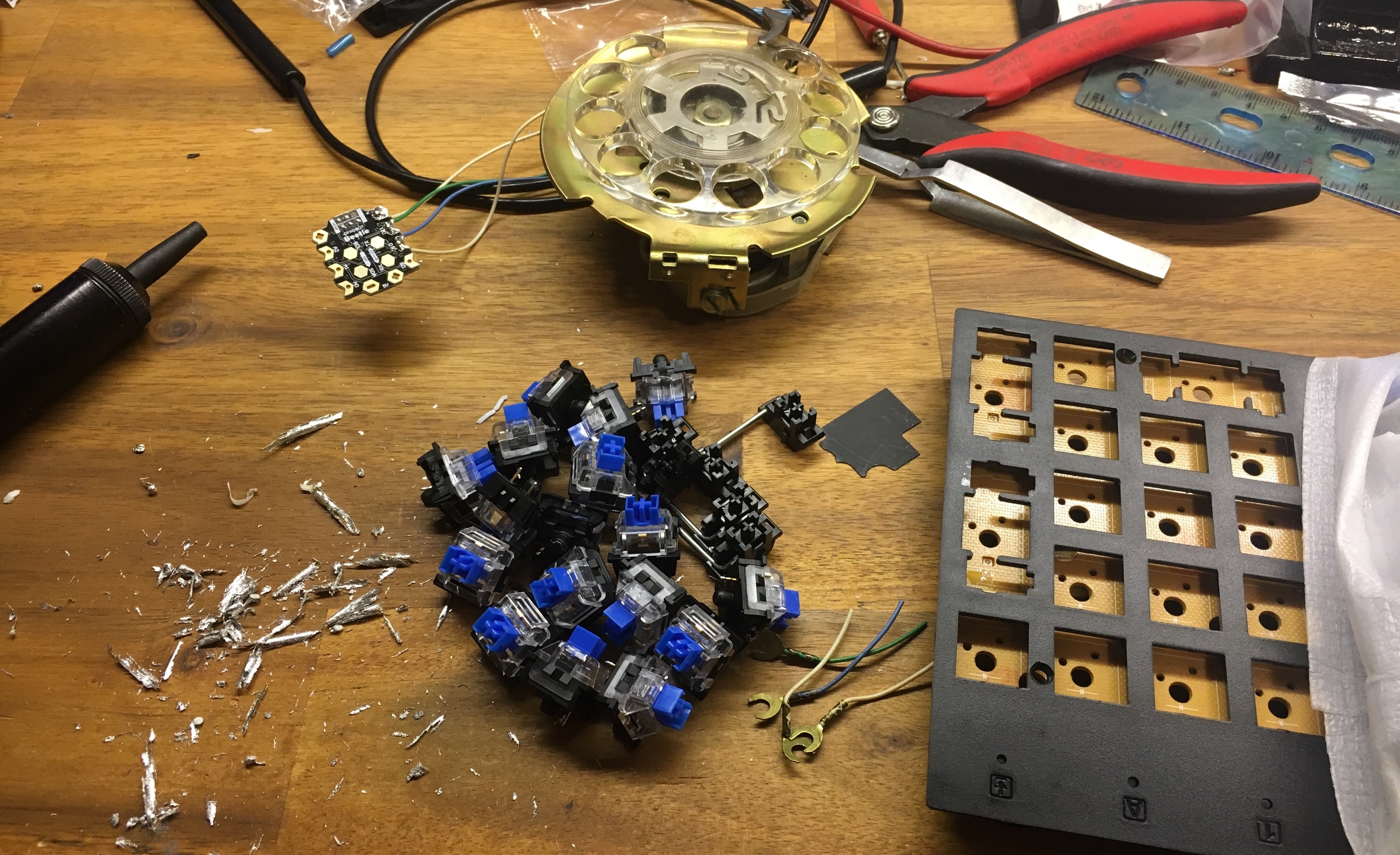
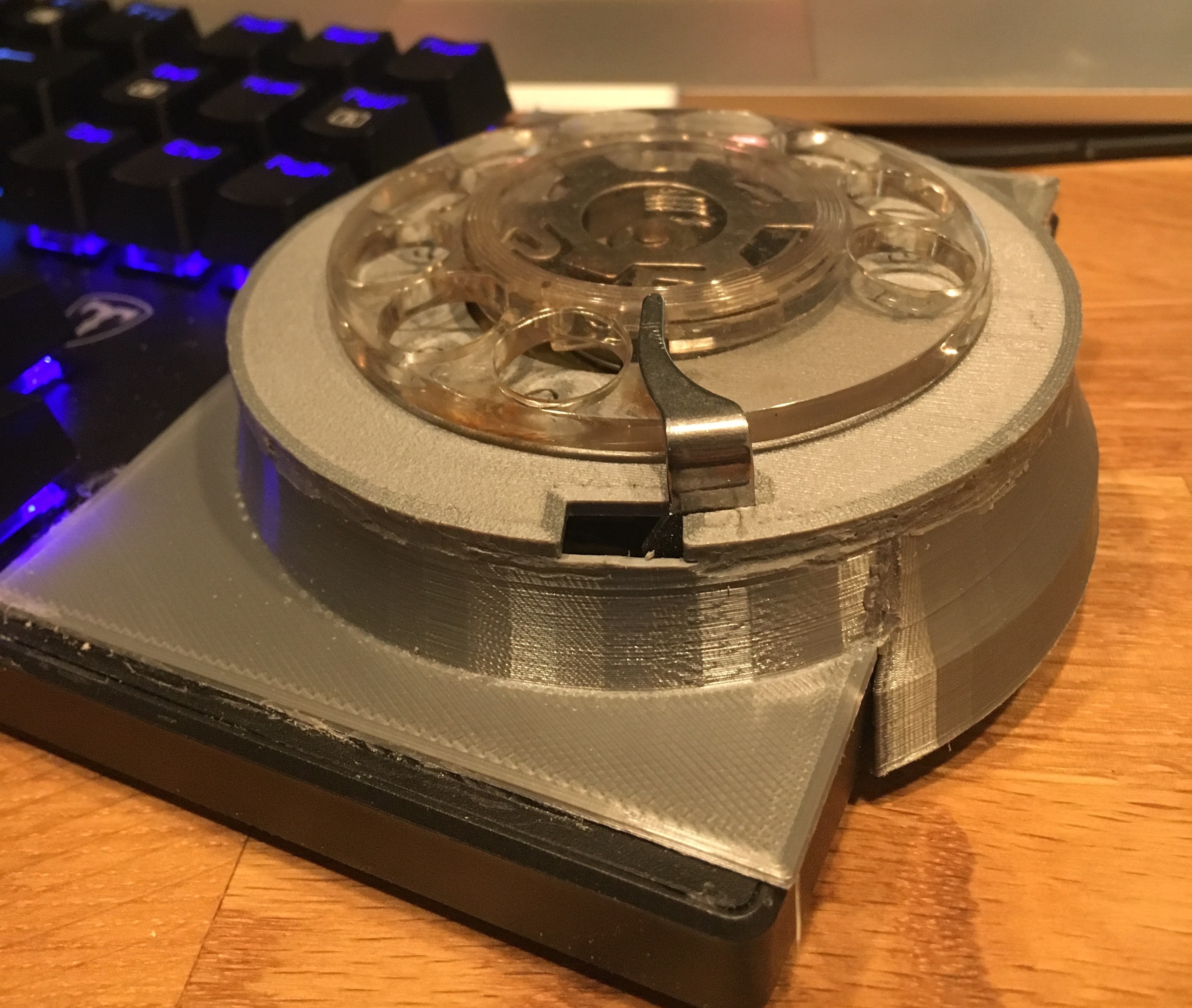
Resting the base of the dial on top of the PCB would have been an option here, although it would make the dial itself sit very high in the air.
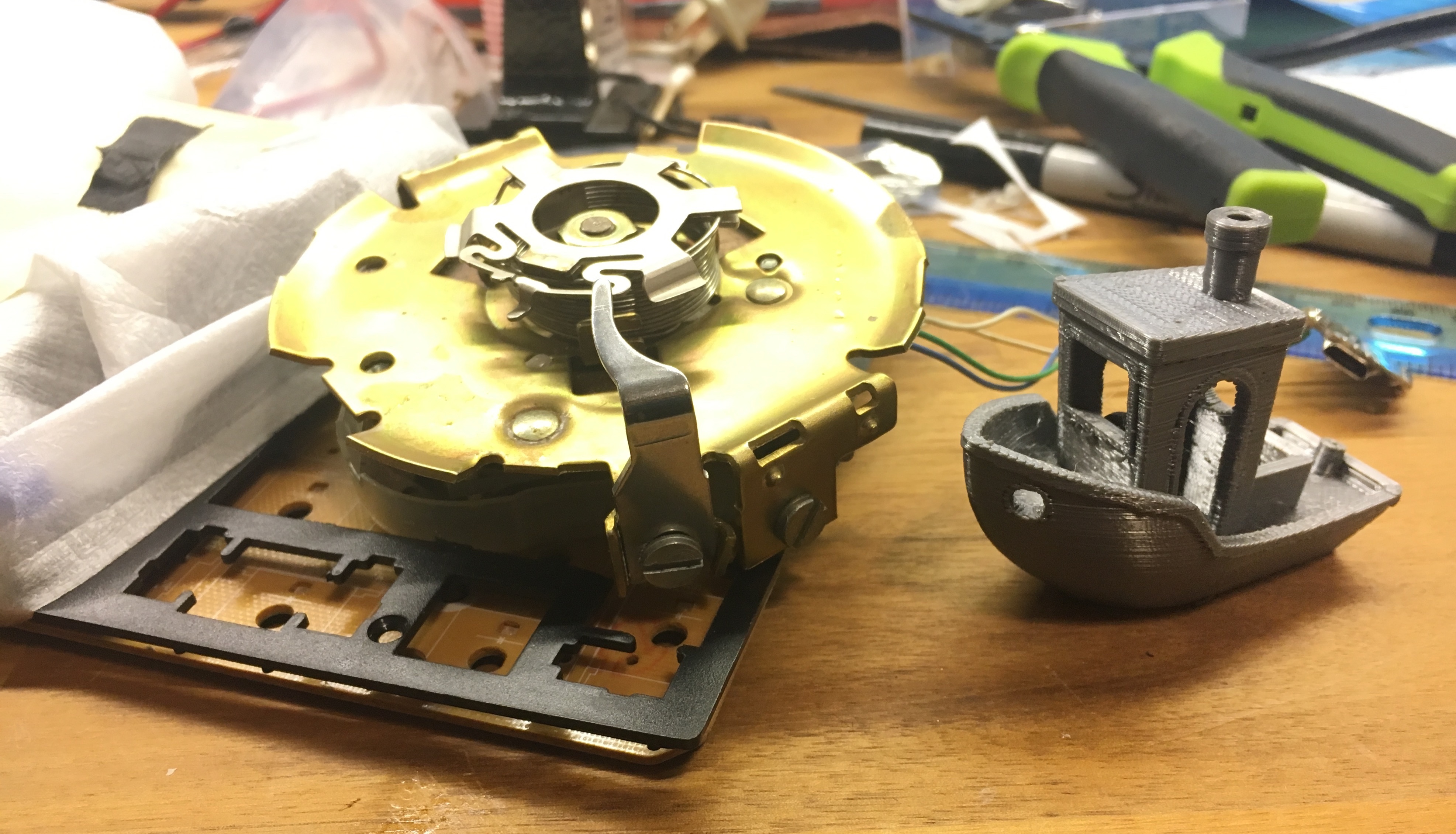
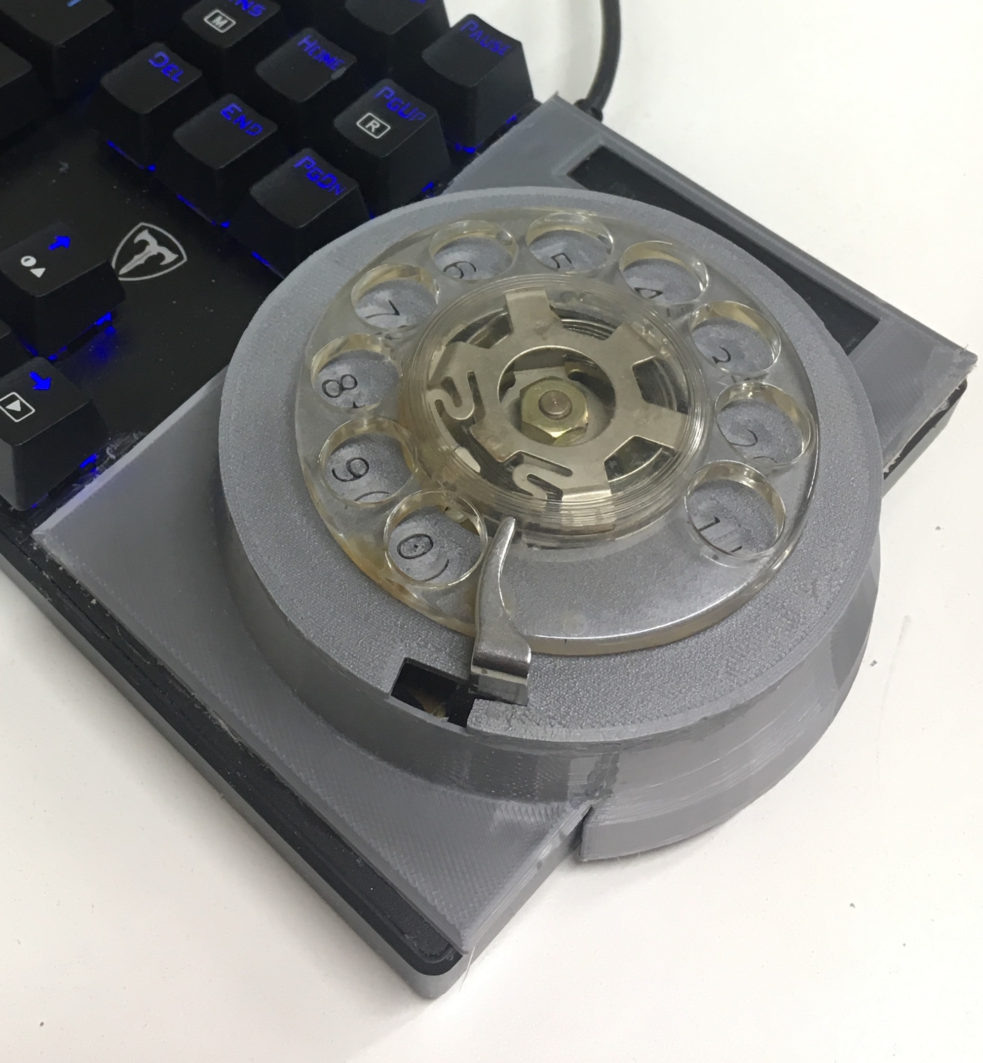
But then I realized that cutting the PCB away underneath the dial would allow the dial to sit at keycap height, as below:
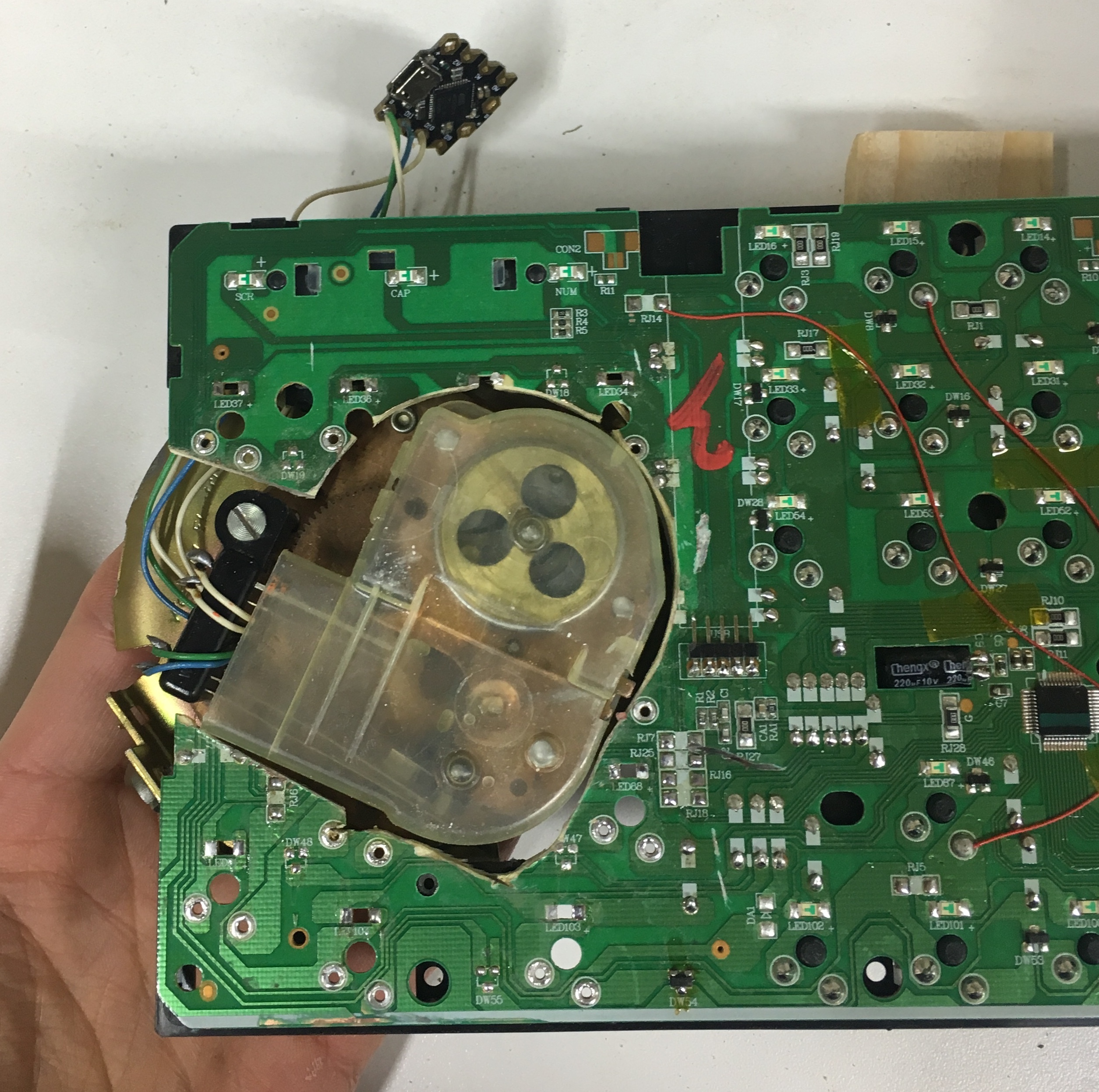
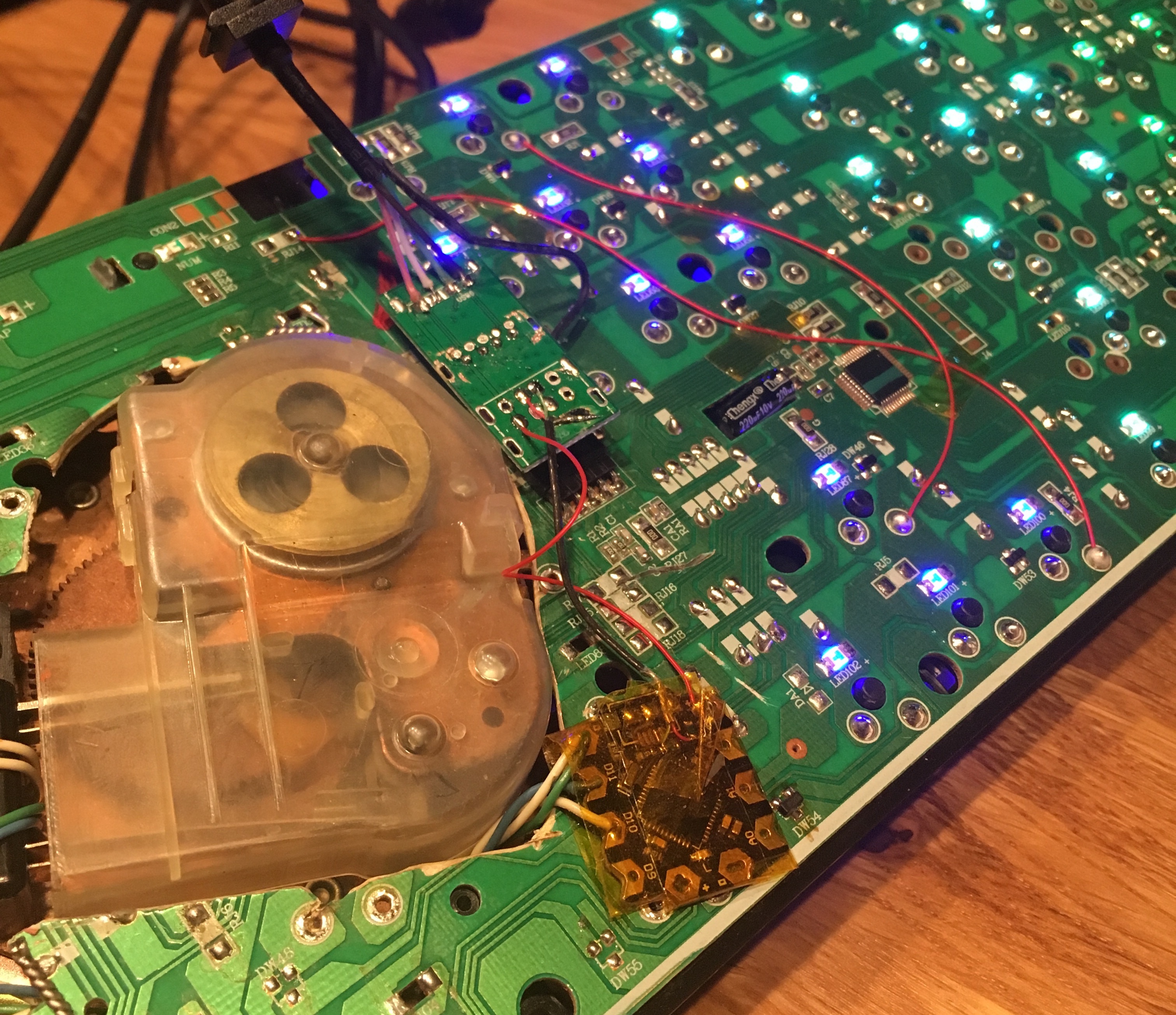
This would entail cutting through the traces on the bottom of the PCB that allow the keyboard to scan all the keys to find out which ones have been pressed, so I spent a lot of time probing the traces with a multimeter and making jumpers to replace those traces.
However, I wasn’t thorough enough and had to add some more after plugging the board in and realizing I’d broken the arrow key cluster. Fun fact - the keyboard matrix on this board is also used to enable the LEDs individually, so if the keyboard can’t light up a given key, it won’t be able to read it either.
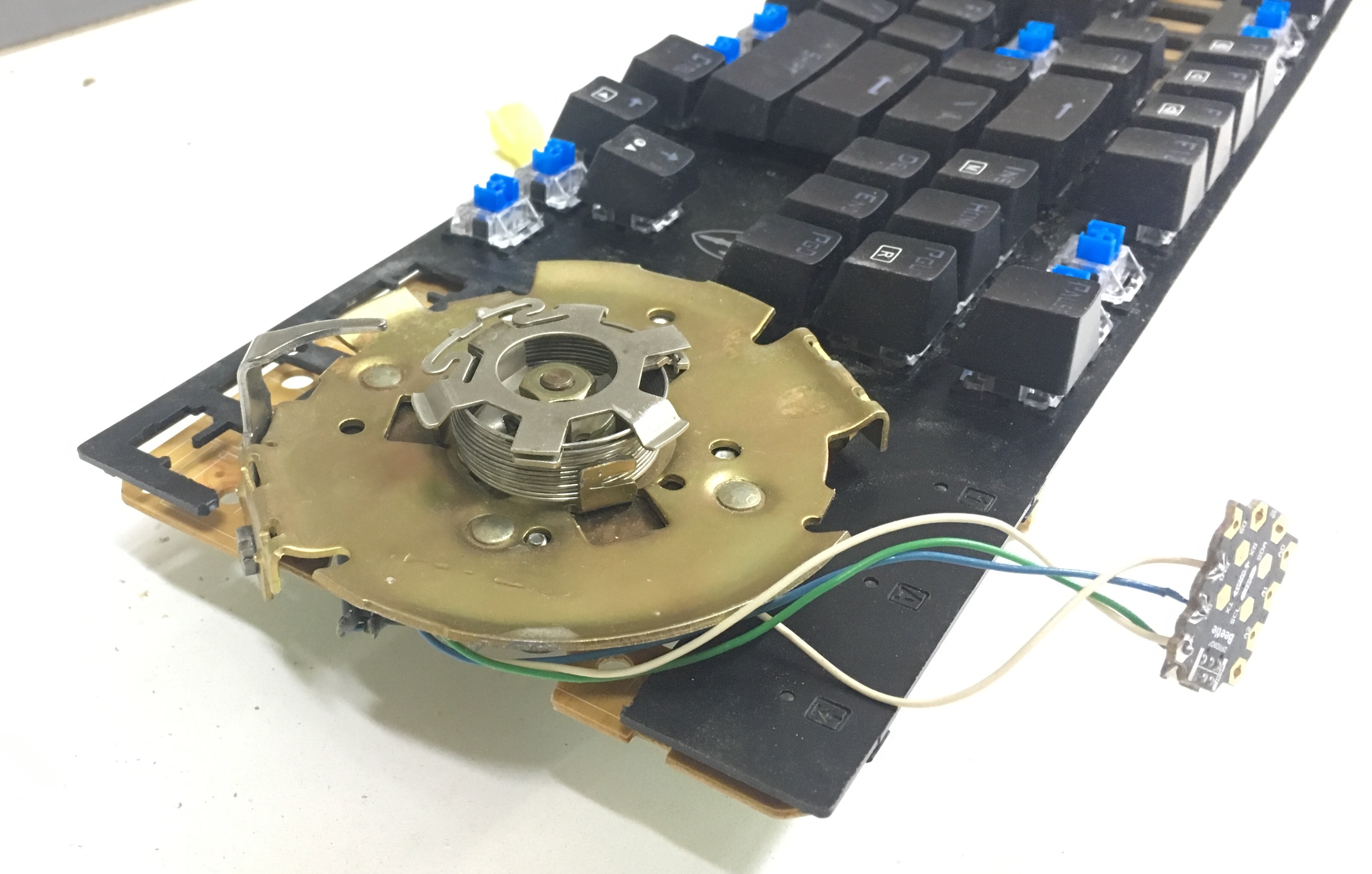
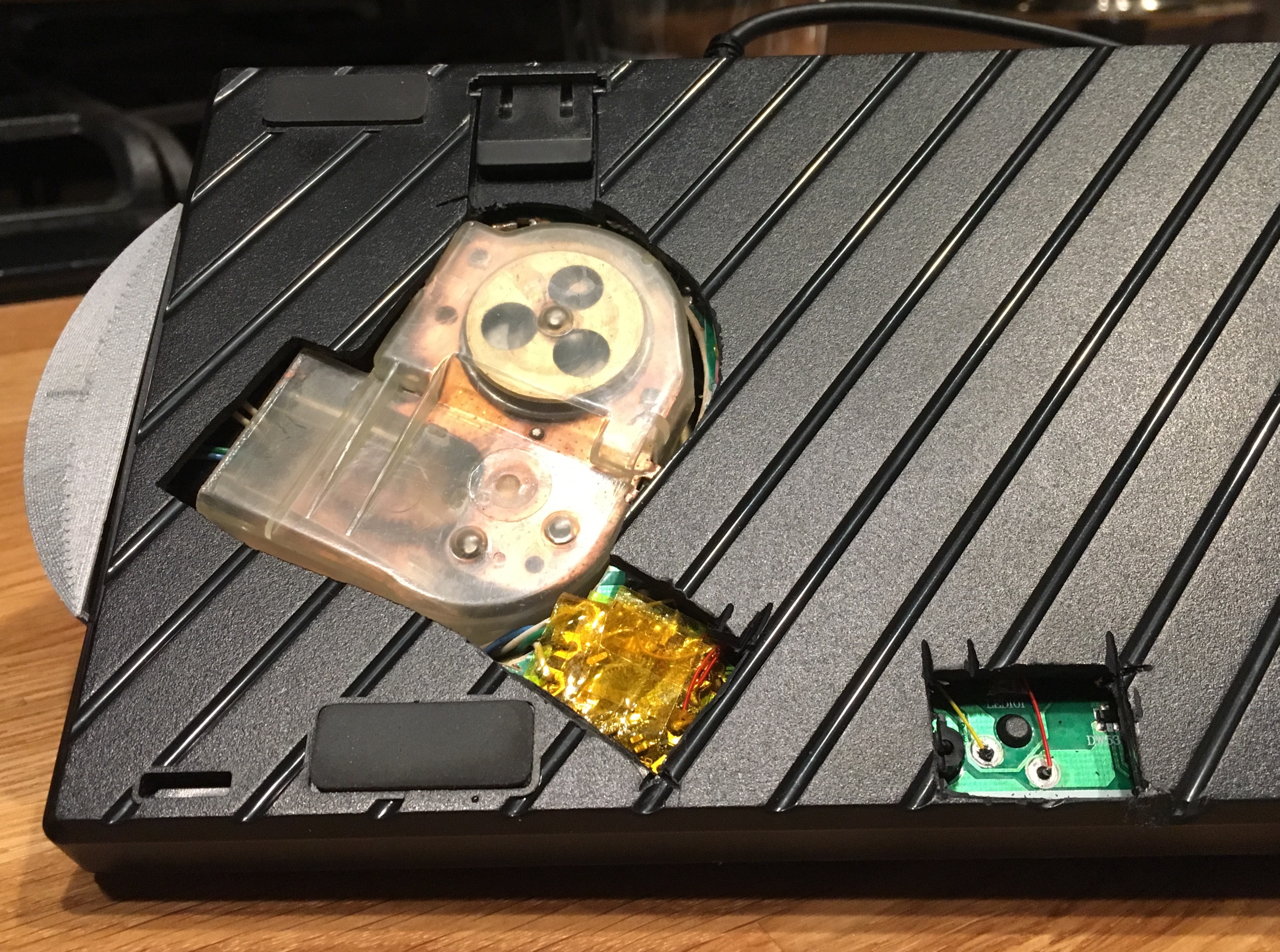
After attacking the keyboard with a hole saw, an oscillating cutter, and a Dremel tool, I was able to safety-wire the dial to the remnants of the keyboard PCB.
This also allowed me to finish up the USB wiring and confirm that I hadn’t fried anything important yet (note that the keyboard lights are on - this indicates that at least power is being delivered).
3D Printing
I decided to 3D print a shroud to hide the internals of the dial and make this look a little bit less like Frankenstein’s monster’s keyboard. Oh, and I suppose legends for the special characters are important as well since some people may not have them memorized…
I hadn’t really designed anything in 3D CAD prior to this project, so I took the opportunity to learn just enough OpenSCAD to make all my mechanical engineer friends run away screaming. I mean just enough OpenSCAD to perform the orbits and elevations I needed to describe a shroud that would notch into the dial’s thumbrest and conform to the keyboard’s inclined base.
In all seriousness, though, having a functionally-defined language for creating solids is great, and the fact that everything is parameterized by definition makes it very simple to go back and tweak things without having to throw away lots of work.
(Ironically enough, I managed to lose the OpenSCAD file that defines the dial legends, so this render was made by importing an STL into OpenSCAD…)
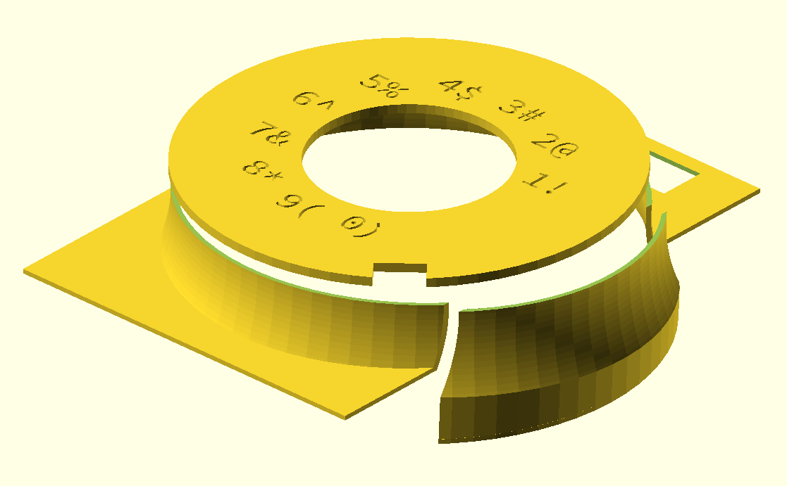
It was a little trickier to get the legends where I wanted them, but I eventually got close enough by using OpenSCAD’s SVG export feature and printing dials out until I got an angle I thought looked reasonable.
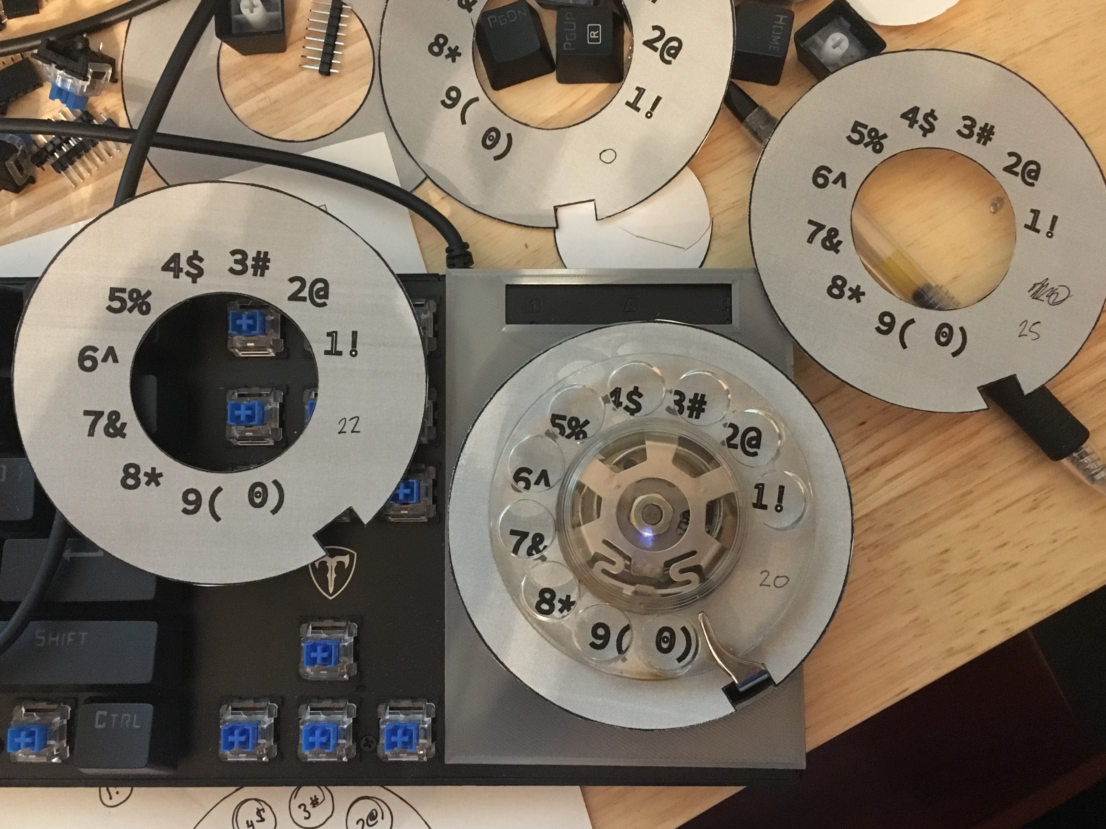
Of course, the final 3D printed part was still moderately misaligned and I had to carve a notch in it to get the angle right.
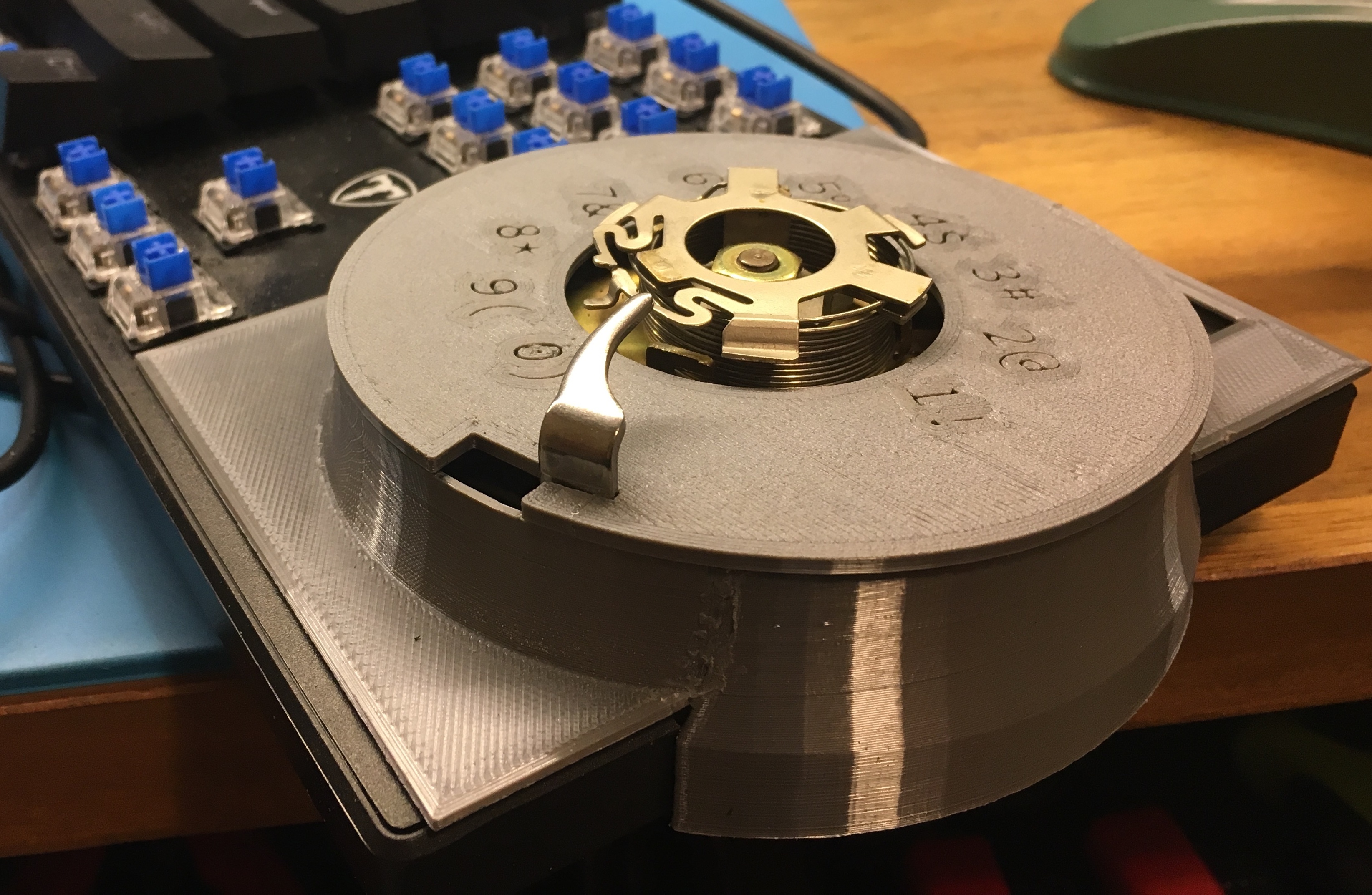
Beyond that, I had to cut down the metal of the rotary dial base a little bit but was able to get it all to fit together after a bit of sanding. I was able to use friction stir welding to join all three pieces together by chucking a piece of filament in my Dremel and running it along the seams. This is significantly harder than it sounds and gives you a real appreciation for the people who do this at the industrial scale with stainless steel for, e.g., the SLS rocket’s fuel tanks.
Parametric keycap detour
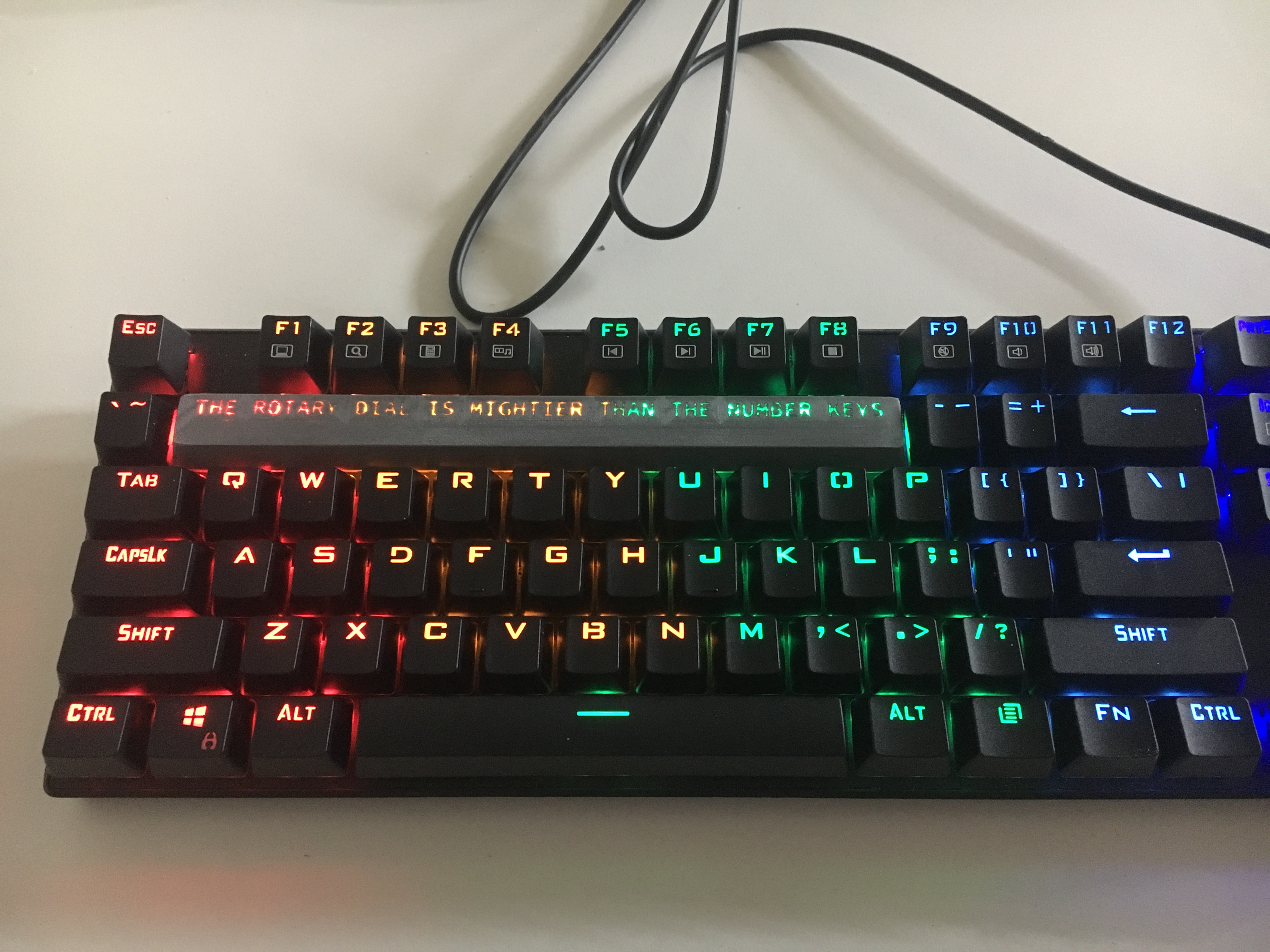
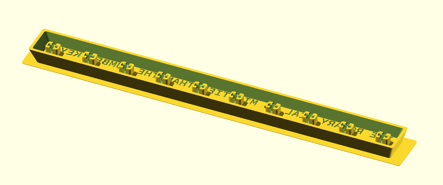
Just ripping out the number row to force the use of the rotary dial would be funny enough, but I decided that it would be more fun to print a custom 10U keycap that would match the profile of the existing keys and provide a legend for the keys’ LEDs to shine through. This was possible thanks to this incredible parametric keycap generator for OpenSCAD that I found on GitHub.
include <./includes.scad>

$stem_positions = [[19.05*-4.5,0], [19.05*-3.5,0], [19.05*-2.5,0], [19.05*-1.5,0], [19.05*-0.5,0], [19.05*0.5,0], [19.05*1.5,0], [19.05*2.5,0], [19.05*3.5,0], [19.05*4.5,0]];
$inset_legend_depth = 3;
$font="Source Code Pro:style=Semibold";
oem_row(1) upside_down() u(10) dishless() legend("THE ROTARY DIAL IS MIGHTIER THAN THE NUMBER KEYS", [0, -0.8], 4.5) key();
Due to Cura being rather naïve when it comes to slicing with internal cutouts, I had to define a brim by hand to keep the keycap from peeling off the bed. Yes, OpenSCAD projections are horrendously compute-intensive and so there’s probably a better way to do this…
difference() {
    scale([1.07, 1.5])
    linear_extrude(height=0.2)
    projection(cut=true) oem_row(1) u(10) upside_down() dishless() key();

    linear_extrude(height=0.2)
    projection(cut=true) oem_row(1) u(10) upside_down() dishless() key();
};
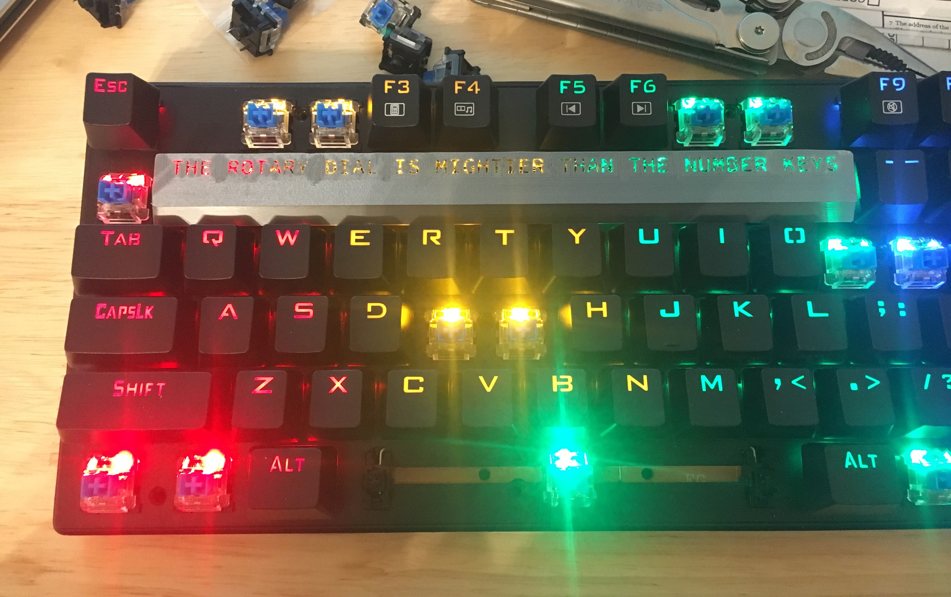
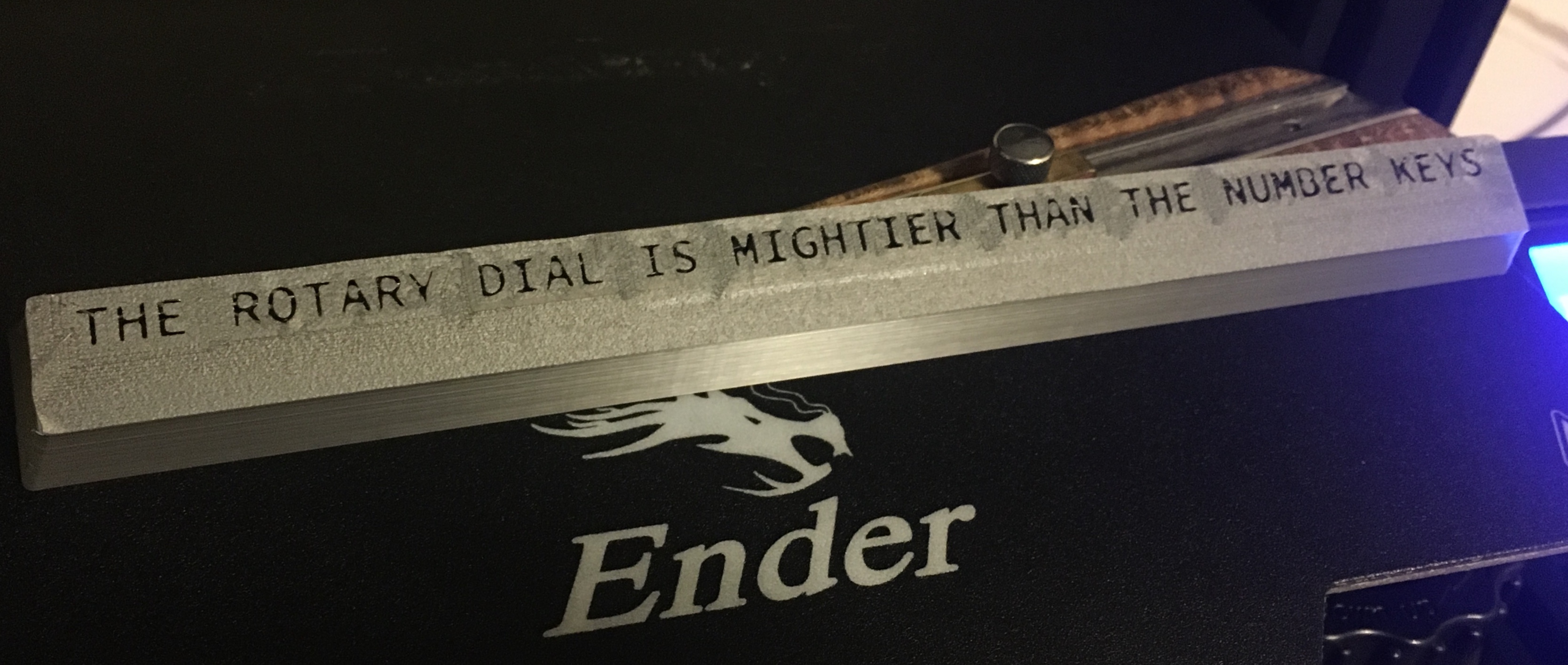
Once I had the stabilizing keyswitches installed to my satisfaction, I stuck a piece of masking tape over the top of the keycap (covering the legends) and poured what remained of a fairly dead bottle of superglue in to fill the legends. Two days later, it had finally cured all the way through… Multiple thin layers are probably much wiser since superglue cures with exposure to moisture and so the bottom of the legends (i.e. the portion closest to the top of the keycap) took a long time to cure.
Yes, it does in fact type out the rotary dial is mightier than the number keys when pressed; I wired all three of the switches supporting the keycap in parallel and connected them to an unused input pin on the Arduino.
Final Assembly
My shroud wound up needing to be hotglued down to the keyboard (with some shims since I’d mis-measured the incline…), which also trapped a bunch of the screws that hold the keyboard together. Good thing I would never have wiring errors, right? ….Right?
Well, it turns out that I cut one of the traces for the down arrow key somehow. Can’t imagine how that could have happened. While I maintain that vimkeys should be adequate for everybody, non-functional keys are a bit of an embarassment, especially when one has glued the keyboard shut.
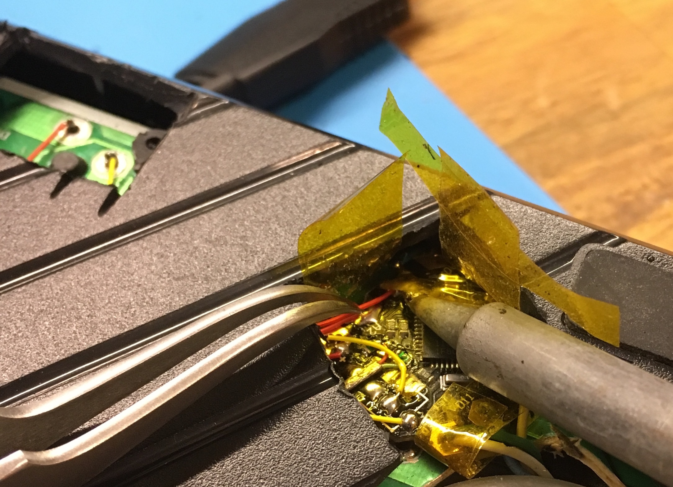
I solved this by using a cutoff wheel on the Dremel to slice into the back of the keyboard underneath the down arrow key and near the Arduino, allowing me to fish wires from that key to the Arduino and gain further appreciation for those who build ships in bottles. Thanks to the single-sided nature of the keyboard PCB, it was simple to isolate the switch’s legs from the keyboard circuit with a solder sucker and then some heatshrink pieces.
Another problem was a little more pernicious - I snuck it into a coworker’s office while he was out on his lunch break but plugged it into his KVM. Unfortunately, the KVM only listens to HID devices like keyboards and mice, which means that my clever USB-hub-in-the-middle solution wasn’t recognized and consquently meant that the keyboard didn’t work at all. How embarrasing…
Reactions
What is this?
(tries to type his password in twice using the laptop keyboard but fails)
Does it actually work?
(it does)
Oh my goodness.
This must be a [Squidgeefish] creation.
… What does this do? The… Rotary… Dial… Is… Mightier… Than… The… Number… Keys…
It makes me absolutely sick that anybody has enough time on his hands to make something like this.
Hi IT, I’d like to put in a request.
It is surprisingly enjoyable to use; I would absolutely buy one of these if it were a commercial product. And if the number row worked.
It is completely unacceptable that an engineer wouldn’t test his product in all possible use cases; this will be going on your annual review…
Is this your abomination against God?
More Pictures