Fibonacci128 SAO

Background
If you’ve spent enough time looking around at electronics online, you’ve probably seen or heard of the Fibonnaci/Fermat spiral boards made by Evil Genius Labs. If you haven’t, you definitely need to check out their site or their Tindie store; the hardware is excellent, and the software generates absolutely mesmerizing patterns. Heck, even the PCBs themselves are fascinating if you’re as much of a nerd as I am…
Over the last year and a half or so of occasional evenings and weekends, I’ve been working on designing and assembling an alternate version of the One-Inch Fibonacci128, with the intent of making an extremely bright/dense SAO conference badge add-on. If you attended Hackaday Supercon 8 this November, you probably enjoyed the dubious pleasure of being blinded by this project at least once.
What is an SAO?
For the past several years, technical conferences have been going beyond simple “My Name Is…” nametags, instead creating PCB-based badge designs of various sophistication. While these badges started off as simple PCB art with the requisite blinking LEDs, they quickly advanced to the point of being complex Linux-capable FPGA systems or front-panel emulators for bespoke 4-bit computer architectures, to choose from Hackaday Supercon badges alone.
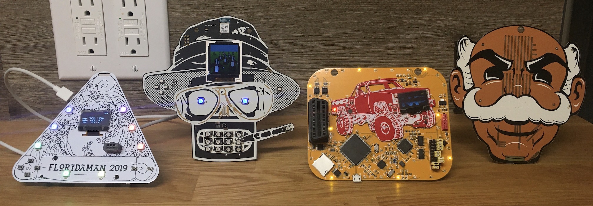
Here are a few badges from a friend’s collection (from left to right: the FLORIDA_MAN 2019 Badge, AND!XOR’s DC25 badge, the Car Hacking Village badge from DEFCON 25, and Brian Benchoff’s Mr Robot Badge (also from DEFCON 25)):
At some point, people decided that the badges were looking a bit lonely and needed their own badges, which led to the creation of the SAO (Sh*tty/Simple/Standardized Add-On) “standard,” as chronicled by Brian Benchoff himself. This standard specifies the usage of a 2x3 keyed box header with 3.3V power, as well as an I2C interface and two GPIO pins.
These SAOs have tended to remain relatively simple and blinky, providing an excellent starting point for anybody wishing to dip their toes into PCB design, electronic art, or small-run production headaches. However, SAO complexity is starting to increase as well, with the focus of this year’s Hackaday Supercon badge being SAO interconnectivity over I2C.
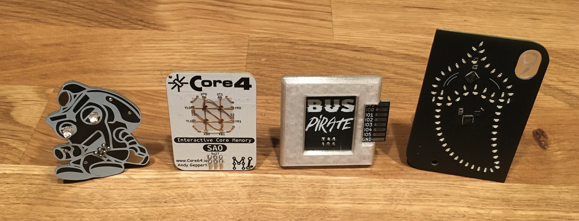
Here are a few examples of SAOs (from left to right: AND!XOR’s “Snackey Jr Jr”, Andy Geppert’s SAO Core4, Tom Nardi’s 70% scale Bus Pirate 5 SAO, and true’s Peppercon 9 addon):
At DEFCON 31, I saw an SAO that looked like one of the Fibonacci designs, but my inner engineer started yelling at me that the pixel density was much too low.
One-Inch Fibonacci128
It turns out that Evil Genius Labs has already made an extremely dense One Inch Fibonacci128 board, cramming all 128 RGB LEDs into a one-inch-diameter circular PCB. The trick here is the usage of the absolutely miniscule XL-1010RGBC-WS2812B RGB LEDs, which measure only 1mm on a side and are also compatible with the WS2812B/Neopixel protocol, allowing for easy daisy-chaining.
I considered buying one of these boards and designing an adapter board for the back to make it be able to mount onto a six-pin SAO header, but I didn’t feel like spending that much quality time with my calipers, and I had a feeling it would probably not be hard to lay out the LEDs programmatically and integrate a microcontroller on the backside, all without needing an extra adapter. If I were to be making my own knockoffs, I figured that I could also probably leverage the PCB assembly services of a site like JLCPCB so that I wouldn’t have to stencil, place, and reflow all 128 LEDs. How hard could it be?!
Fast-forward about a month, and I was home sick from work with what I call “fuzz for brains” - while I was conscious, I wasn’t good for much else beyond staring blankly into space. I somehow decided that this would be a great time to try to make my own version of the One-Inch Fibonacci128.
Making the LED board
After an extremely short-lived attempt at laying out a Fermat spiral in KiCad using Python, I started poking around online instead and found this Mastodon thread where the Evil Genius himself (Jason Coon) first discovered these 1010-packaged LEDs and built his board. (I originally thought I found this on Twitter/X, but it is definitely on Mastodon, and everybody has been too polite to correct me…).
Using the then-new feature of KiCad 7 to import a picture as the background of a PCB project, I grabbed a beautifully high-resolution picture of an assembled board and dropped it onto the User.1 layer, scaling it by drawing a one-inch diameter circle on the Edge.Cuts layer and adjusting to match.
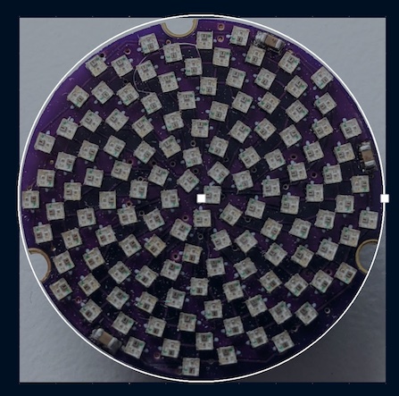
Then I made a footprint for a 1010-package LED with minimal courtyard keepout and dropped 128 instances of it onto the board. I set the rotation step in KiCad to 0.5º so that I could spin the footprints around using the R and Shift-R hotkeys and embarked on an absolutely engrossing journey of placing and rotating all 128 LEDs to match the original.
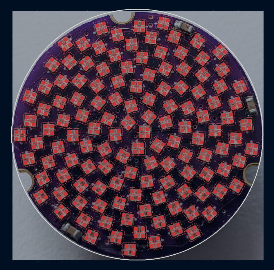
(One fun trivia fact is that I did all the layout and routing without checking how JLCPCB oriented the LEDs for assembly - it turns out that my guess at a logical orientation was exactly 90º off of JLCPCB/LCSC’s. So after doing all the routing, I had to edit my footprint and then spin every LED by 90º so that JLCPCB would install them correctly. That would have been an expensive oops…)
At this point, I set KiCad to let me route 0.15mm (roughly 6-mil) traces at any angle I wanted since I needed all the clearance I could get to avoid trace clearance violations. At some point it might be faster to throw it at the auto-router, but, well, “fuzz for brains,” and I like hand-routing boards anyway.
There are some very cool emergent properties of this layout, though. If you look at the picture below, the most salient item is the data-in to data-out daisy-chain on the LEDs themselves, highlighted in green. It very satisfyingly weaves from the center out to the edge of the circle and then dives back in again.
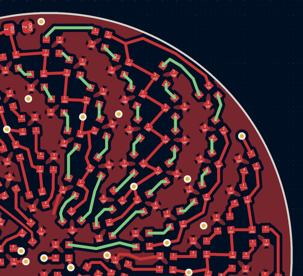
Another fun feature is that creating a copper pour for the ground net wound up creating this pinwheel pattern, with a bonus pinwheel in the negative space used by the power net.

In order to be sure not to run afoul of JLCPCB tolerances, I wound up bumping this to a four-layer board both for the improved clearances and for the ability to run a couple traces on an inner layer (JLCPCB actually wound up emailing me to confirm that I was only using one of the inner layers…). Handily, I happened to make this design choice during a promotional period where four-layer boards cost the same as two-layer ones.
Microcontroller
At this point, I had completed the “how hard could it be!” portion of copying an existing design by taking advantage of a “fuzz for brains” stupor to churn through a pile of tedium. Now I just needed to design the supporting hardware that would actually drive the LED array.
For this, I needed a 3.3V-compatible microcontroller that could handle both generating a framebuffer for all 128 LEDs and interacting with the host badge via I2C. Most importantly, however, I needed a physically small microcontroller in order to fit it into the free space on the back of the board. I decided to go with a SOIC-8 package so that it would be easily hand-solderable.
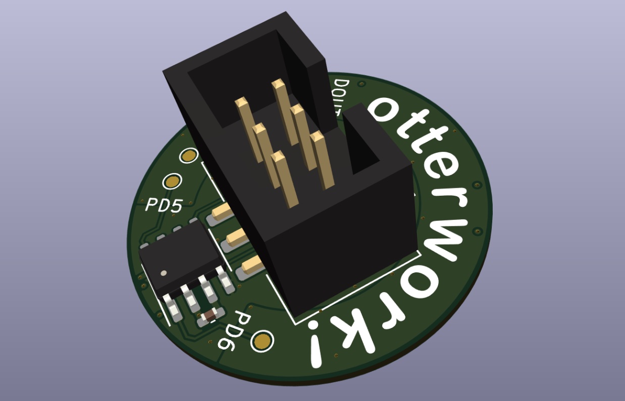
(Why does it say “otterwork”? Well, it “ought to work”/”ought ter work”/”otter work”/”otterwork”, if you get the drift… And, more importantly, why shouldn’t it say “otterwork”?)
My first contender was the venerable ATTiny85 (512 bytes RAM, 8kB flash, 8MHz), but I decided that 512 bytes of RAM would be a bit tight since 128 LEDs at 24 bits of RGB color per LED would fill up 384 of those bytes. Given how I wound up writing my code, this probably would have been fine, but it would be very limited regardless.
Instead, I chose the incomprehensibly more capable STM8S001J3 (1kB RAM, 8kB flash, 16MHz) because of its extra RAM and the fact that I was able to find sample code for driving WS2812s and acting as an I2C device very quickly. I think that I also may have thought it was the more powerful STM32G031J6 (8kB RAM, 32kB flash, 64MHz), but I didn’t realize I’d mixed them up until I’d already ordered parts and boards.
In hindsight, that STM32 or a SOIC-8 CH32V003 (2kB RAM, 16kB flash, 48MHz) offer a lot more flexibility (and vastly lower cost in the case of the CH32V003). These could have allowed for much fancier animations, although the ones that I did implement are by no means pushing the capabilities of the STM8.
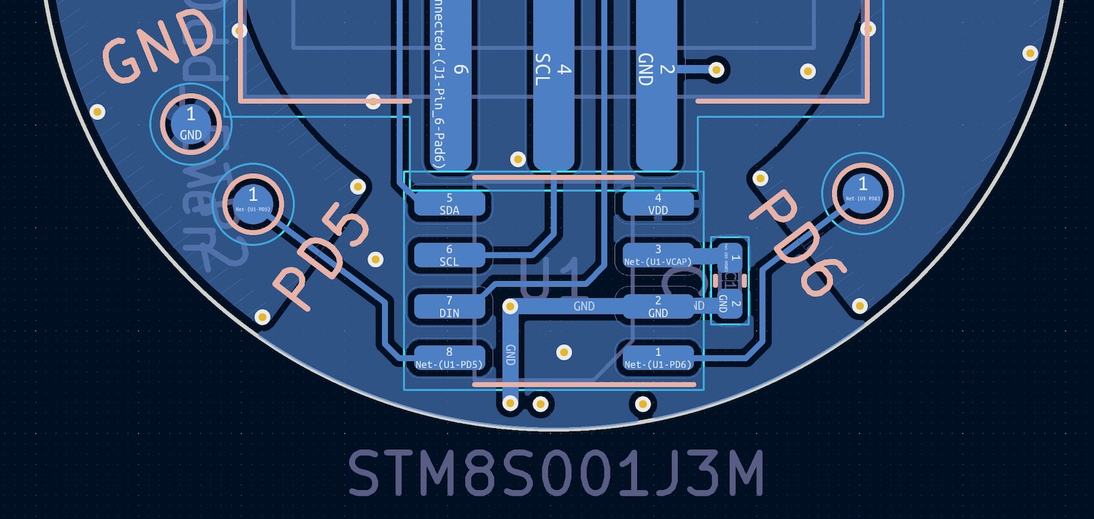
The choice of the STM8S001J3 as my microcontroller very quickly determined my pin assignments - pins 5 and 6 (PB5 and PB4) are connected to a hardware I2C peripheral as I2C_SDA and I2C_SCL, respectively. Pin 8 is used for reprogramming the microcontroller via the “Single Wire Interface Module” (SWIM) protocol, and I chose to use Pin 7 (PC5) to drive the LED array, leaving Pin 1 (PD6) free for shenanigans.
Design for Manufacture
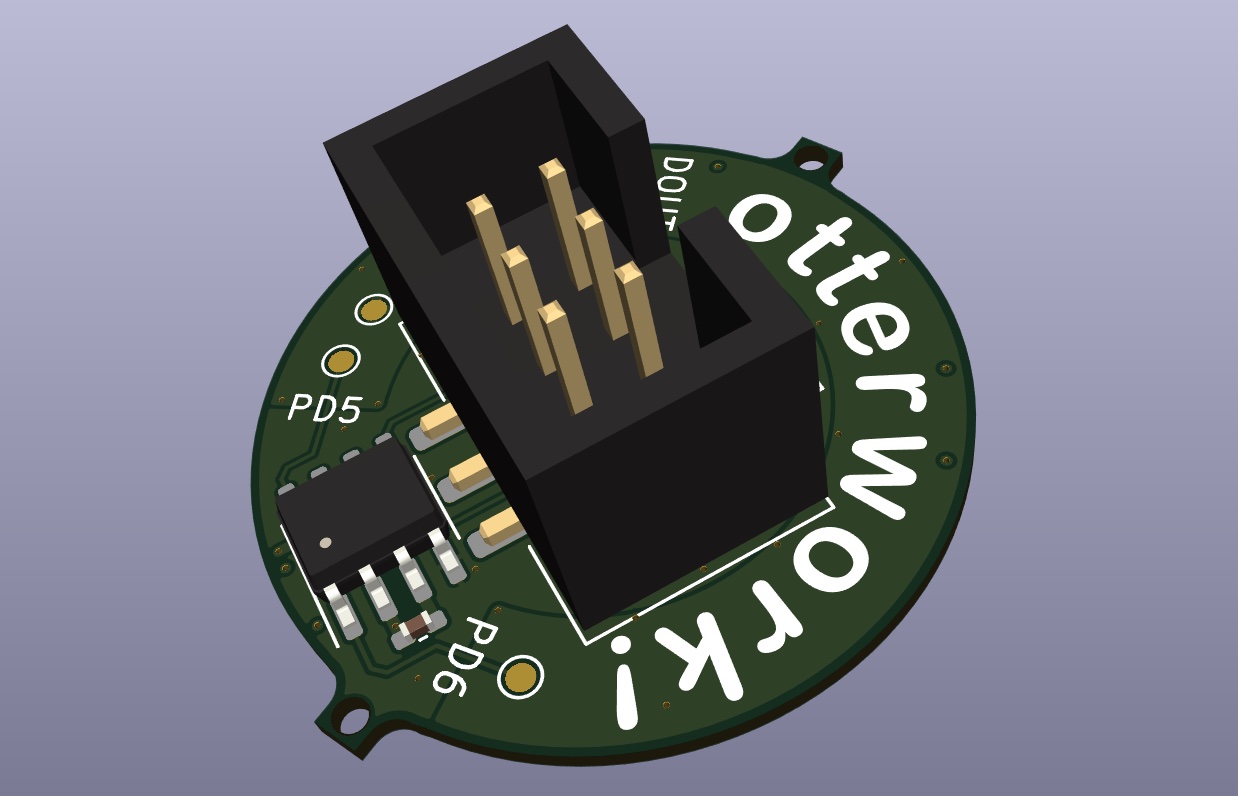
This was my first time designing a board to be assembled in a factory, which meant that I had to make some alterations. The most obvious change was that I needed to add a pair of mounting holes per JLCPCB’s specification so that they could hold and align the boards when stenciling and assembling them. I wound up bodging the bare minimum mounting tabs into my Edge.Cuts layer and then fighting DRC until I got the outline to be a closed polygon again.
Besides the LED rotation snafu previously described, I did have to make a couple choices based on JLCPCB’s pricing. They charge a change fee per unique component used as well as a (much smaller) fee per instance of each component installed. In addition, the “economic PCB assembly” service only populates one side of a circuit board.
In this case, I decided that I was fine with installing four 0402 capacitors on the top of the board and doing the whole bottom of the board (SAO header, bypass capacitor, and microcontroller) myself for the cost savings. After all, the whole reason I was going with the assembly option was so that I wouldn’t have to paste and place all 128 LEDs by hand (it is probably not too bad with a stencil and microscope, neither of which I have at home).
And those cost savings were insane - splitting board cost, component cost, and assembly fees across the five boards I ordered, I wound up paying JLCPCB just under $10 per board, which is a testament both to the power of Chinese manufacturing and the dangers of unleashing a “fuzz for brains” [Squidgeefish] upon a problem which didn’t really need to be solved.
Revision One
A few weeks later, I had five unbelieveably dense LED carrier boards in my mailbox.
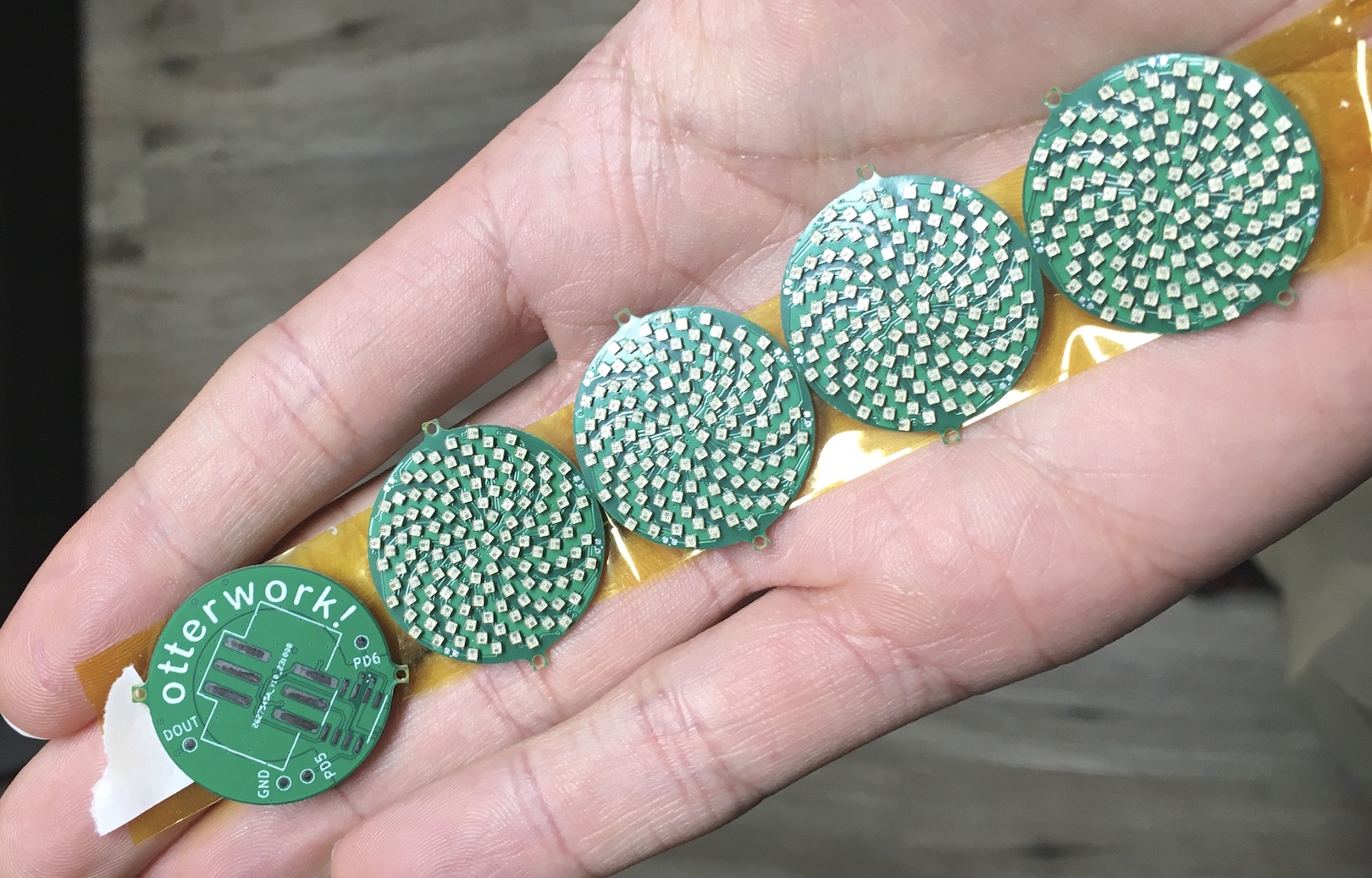
While a sensible person might have taken this opportunity to write firmware for the STM8, I, uh, didn’t actually get around to that until a year later. Why procrastinate when you can save it for tomorrow?
Instead, I hooked up a Raspberry Pi Pico (not pictured, and I lost all the driving code in an unfortunate accident involving macOS temporary files, the Arduino IDE, and sleep modes) to the data input pin for the LEDs so that I could try it out.
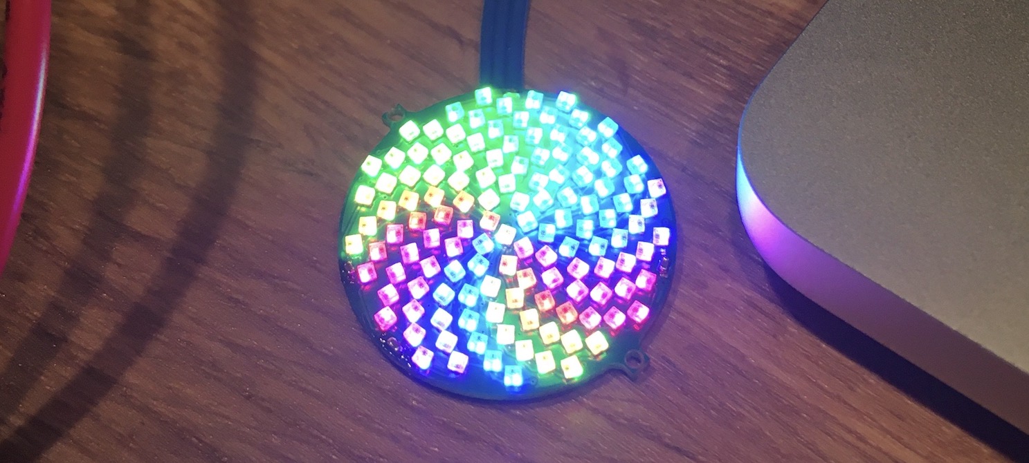
With FastLED, a few Adafruit graphics libraries, and the LED position mapping from Jason’s GitHub, I was able to get bitmapped fonts showing up on this hilariously non-rectilinear LED display.
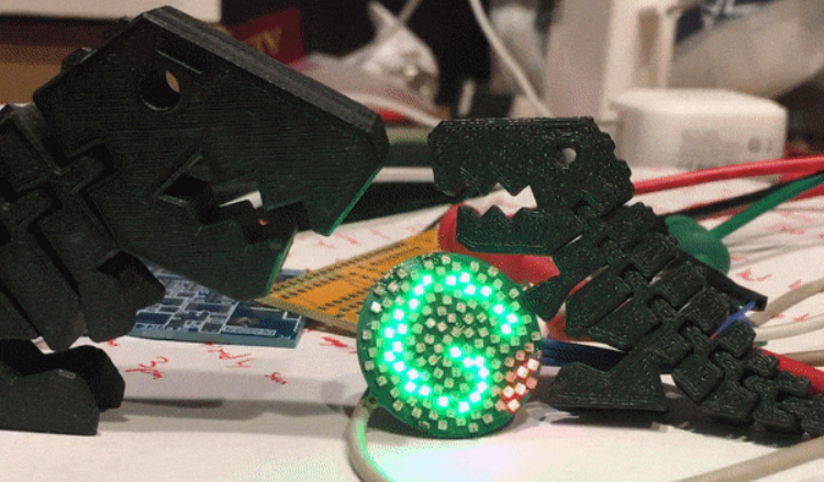
At this point, I showed a friend from work, who promptly informed me that he needed one to go on his badge at Supercon 7 - firmware and microcontrollers were unnecessary if he could just plug it straight into the badge and repurpose an I2C pin for WS2812 output…
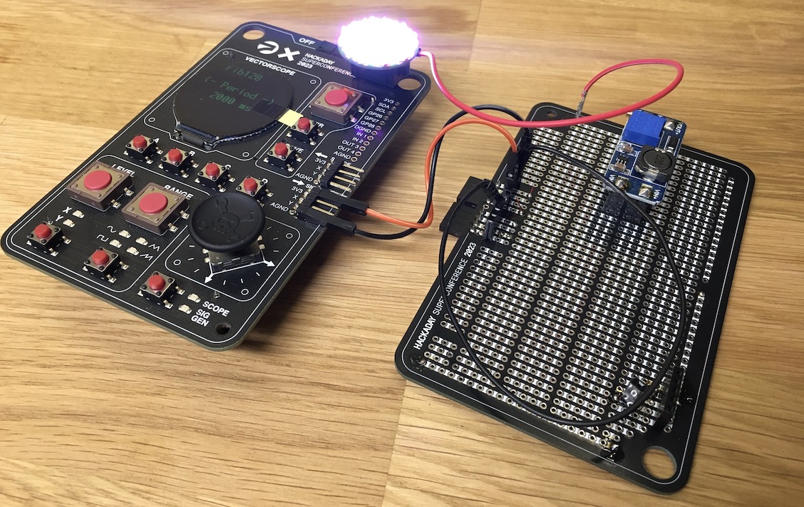
Unfortunately for him, the (otherwise outstanding) Vectorscope badge powered SAOs directly off the dual AA batteries on its back rather than the buck-boost regulated 3.3V on the integrated Raspberry Pi Pico. Not only did the 128 LEDs draw the batteries down in short order, they also exposed an interesting failure mode - while the LEDs are nominally rated for 5V operation, they work happily at 3.3V until they manage to drag the voltage down far enough to prevent the blue subpixels from lighting…
He managed to acquire a 5V boost converter and bodge it onto the badge in true hacker form, solving the problem at the expense of the 1” footprint of the SAO.
The following picture is a dramatic recreation of the bodge since, as far as we can tell, nobody has a picture of the real thing.
Adding a Boost Converter
I mostly left this project alone for the next year or so until I was informed that I absolutely had to attend the next Hackaday Supercon. I’m not one to argue with the facts, so I ordered my early-bird tickets within minutes of the Eventbrite site going live. A few days later, I had KiCad open again, trying to figure out how to salvage the board design to be able to work with non-5V power.
PCB Design
As with many questions in life, the answer came to me by means of a Digikey parametric search. I had already figured that I would need to make some sort of interposer PCB that would mount on the back of the original SAO board and boost the voltage up to 5V, but I’d never designed a boost converter circuit before. Luckily, Digikey search came through with the TI TPS613222ADBVR 5V 2.5A boost regulator in a charming SOT23-5 package.
I unabashedly cribbed from the reference designs in the datasheet and slapped together a schematic that used recommended parts for both the bulk capacitors and the primary inductor, although I chose a PMEG1020EH,115 for D1 since it had a smaller package.
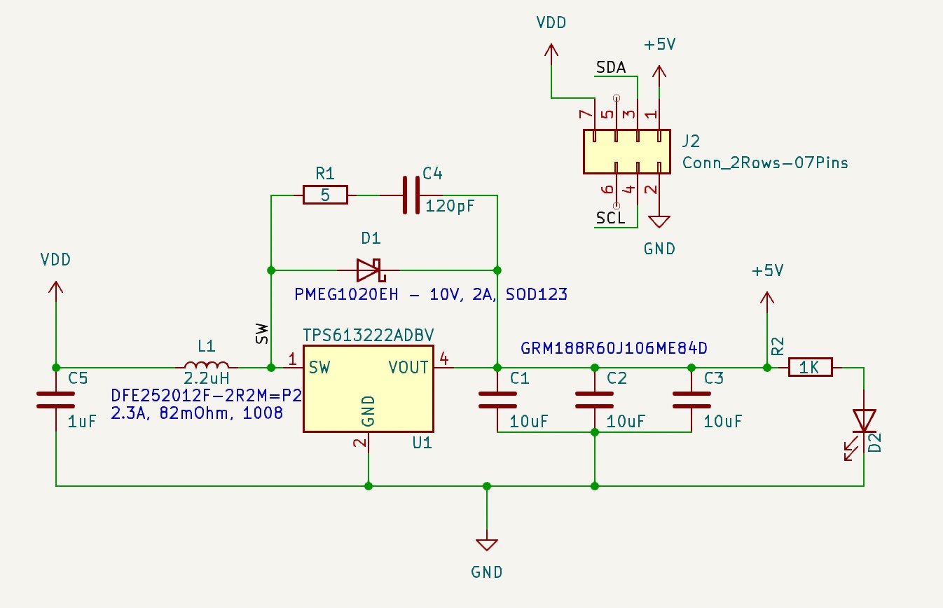
I think the most interesting thing with this board is how I’m intercepting the power pins on the SAO header. I have an internally-castellated cutout that allows me to connect the boost converter board to the LED board’s SAO header footprint. Five out of the six pins connect straight through, but the power pin has a special bifurcation - the castellation needs to be the 5V output from the boost converter, but the surface-mount header pad is the 3.3V input from the badge. The picture below illustrates this relatively well, with the one caveat being that I needed to add a piece of Kapton tape over the 5V castellation connection. It might make your brain a little warm at first, but it is rather elegant.
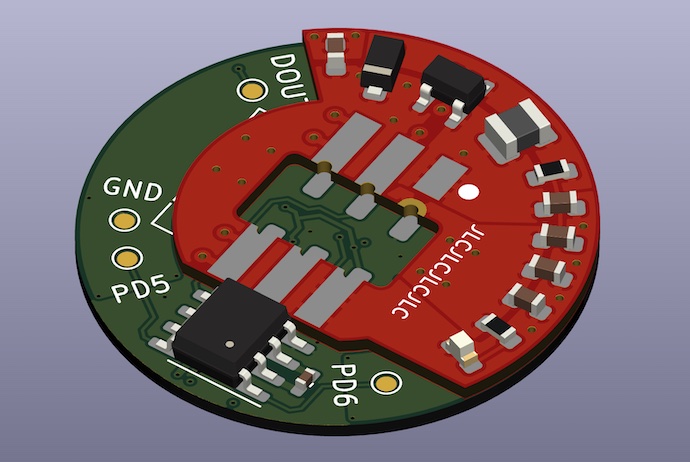
Note, however, that this didn’t work quite as slickly in practice as I was hoping - the PCB milling for the internal cutout tore up these plated through-holes and so they didn’t all come out as nicely castellated as they look in the render. They were very easily salvageable with some magnet wire to get the solder to flow up where the castellation had disappeared, though.
Also note that I was able to import the LED board into this new project as a 3D model - KiCad has excellent .wrl support, and so I exported the prior project as a .wrl and then added it as a 3D model file for the SAO header, which I of course wanted to be centered on the LED board.
I had a lot of fun making this board (which is why it doesn’t strictly follow TI’s recommendations for PCB layout in the datasheet); dusting off my trigonometry to get the proper angles and elevations for uniform radial distribution was a good time, and it also produced the most entertaining F.Fab layer I’ve ever made as a byproduct:
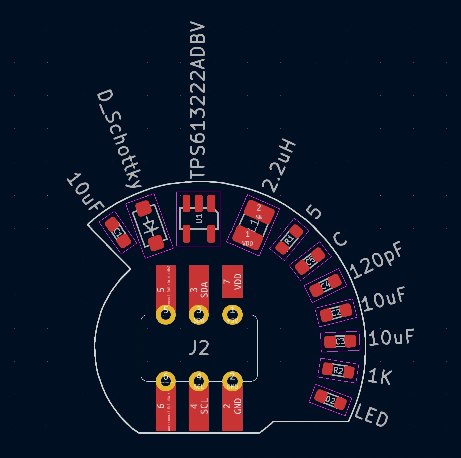
I sent this board off to JLCPCB at what is for me a shockingly reasonable 1AM and got it back a week and a half later.
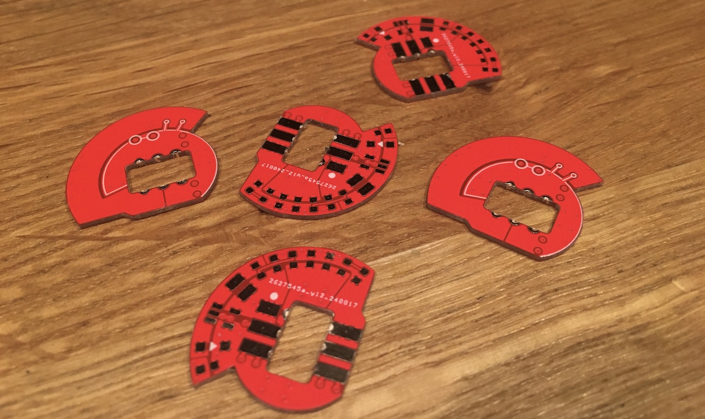
You might be wondering what the deal is with the little bespectacled dorkopod critter. If you aren’t wondering, either you need to look more closely at the back silkscreen in the above picture or you already know…
The dorkopod is another case of emergent behavior in this design; I happened to be looking at the bottom of the PCB in KiCad’s 3D viewer and noticed that my vias and pour boundaries happened to be defining a dorkopod, at which point I had to add some silkscreen to accent it.
Assembly
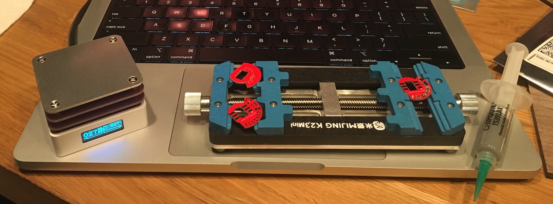
In one of my ill-advised late-night Aliexpress orders, I somehow became the owner of one of these 60W USB-C hotplates. Mine happened to melt its thermocouple off the bottom of the heating element the first time I turned it on, which means that it heats up as quickly as it can. I’ve found that this works fine with my solder paste, but I do need to get some high-temperature RTV one of these days to glue it back on.
Thanks to this Aliexpress purchase and a certain confluence of mail stacking up on my kitchen counter, I was actually able to assemble the first one of these boost converter boards without leaving my seat after eating dinner…
The following picture is the board immediately after reflowing it. Surface tension is magical; I was able to poke a couple misbehaving components with my tweezers and get them to un-tombstone and snap into place quite easily.
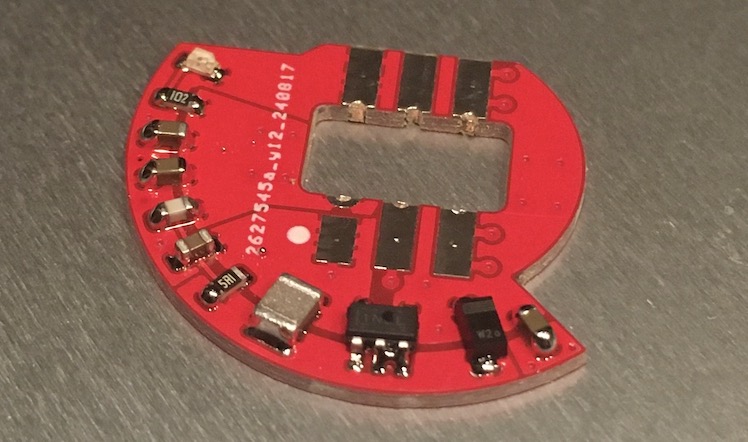
That solder bridge on the SOT23-5 isn’t actually consequential since pin 3 is N/C, but never fear; I fixed it anyway.
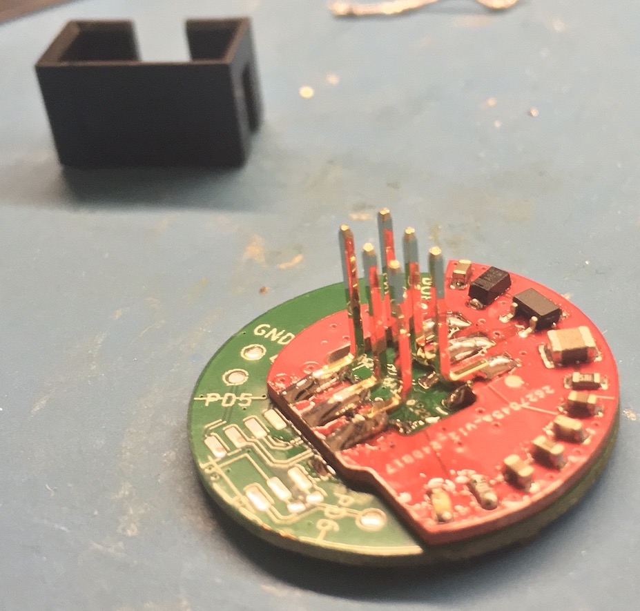
Unfortunately, something about these internal castellations didn’t quite agree with JLC as previously mentioned, and so the installation process was a mite bit technical. After having done five of these now (one in a hotel room the night before Supercon), I think I’ve gotten the hang of it, but it is a bit tricky working with the surface tension of your solder to avoid letting it flow onto the surface-mount pads while still trying to connect to them mechanically.
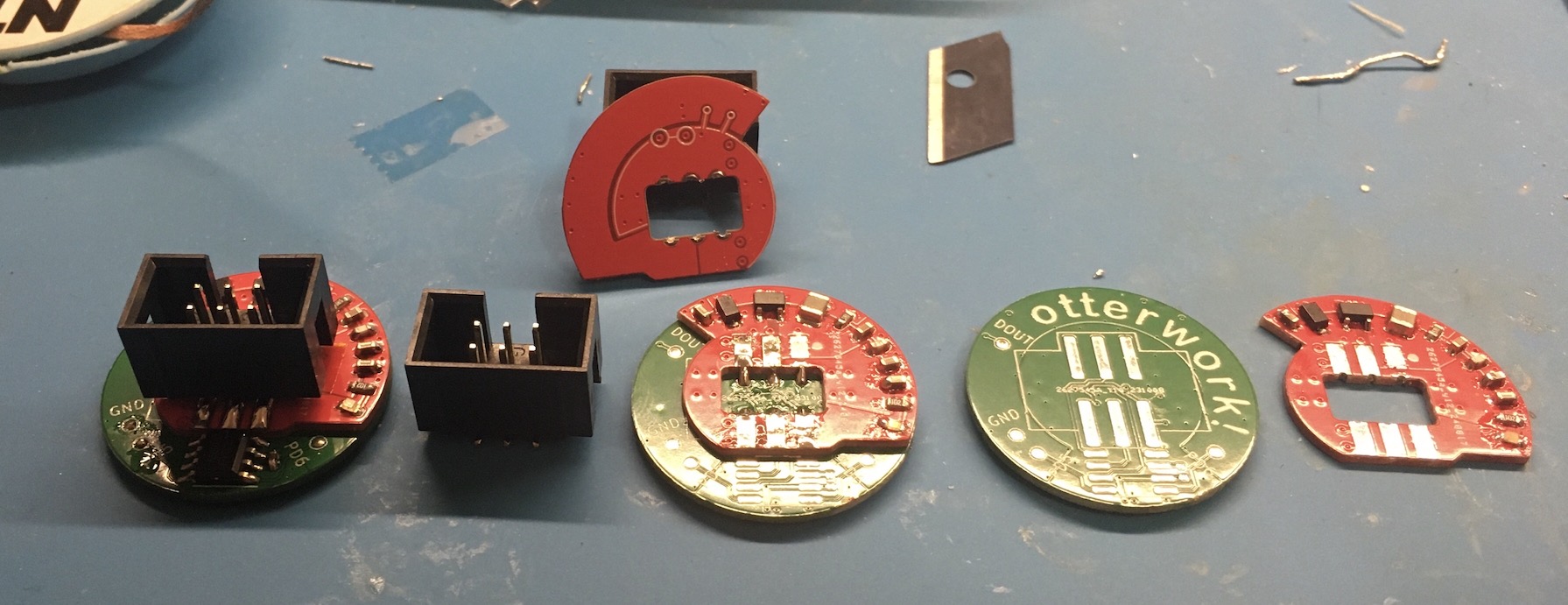
I forgot to install the Kapton on this one before installing the box header, so I got to pry the header shroud off. Pro tip - if you ever need to rework an SAO box header for some reason, do this rather than trying to hot-air it off; that will only end in tears. You can also just slide the shroud halfway up the pins to keep them all aligned while giving you more room to work.
Microcontroller Firmware
To my surprise, I was able to do this in a single evening thanks to the Internet (and specifically the STM8S reference manual).
Das Blinkenlights
I started off by looking around for prior art for driving WS2812-compatible LEDs with an STM8; I found this wonderful gist from stecman (of Unicode Binary Input Terminal fame) that provides a full SCons/SDCC build chain as well as some inline assembly to meet the timing requirements of the WS2812 pulse train. In order to port this over to my board, I had to change the driving pin from pin D4 to pin C5 in both main() and in the ws_write_byte() handler:
void ws_write_byte(uint8_t byte)
{
    for (uint8_t mask = 0x80; mask != 0; mask >>= 1) {
        if ((byte & mask) != 0) {
            // Set pin high
            __asm__("bset 20490, #5");
...

int main(void)
{
...
    // Pin C5 in fast push-pull mode
    // This starts high as the light looks for low signals
    GPIOC->DDR |= (1<<5);
    GPIOC->CR1 |= (1<<5);
    GPIOC->CR2 |= (1<<5);
    GPIOC->ODR &= ~(1<<5);
...
One thing I thought I’d have to change is that the Sconscript is written for an STM8S003 rather than an STM8S001, but it builds, uploads, and runs just fine with the STM8S003 target, so…
In order to program the board, all I had to to was hook up power and ground, as well as connecting the SWIM signal to the PD5 testpad. I was able to do this with a knockoff ST-Link v2 programmer off Amazon with no issues whatsoever.

It is incredibly bright by default; I very quickly chopped the brightness down by dividing each channel’s original 8-bit value by 8 (right-shift 3 bits…) and wound up setting the divisor to 12 so that I could look at the generated patterns directly.
I’m not enormously artistic; I’m much happier messing around with a soldering iron or other hand tool. But if you make a board with 128 LEDs on it, you have to play with the blinky patterns; it’s just required.
Due to the nature of how the LED chain propagates itself, inputting a simple rainbow spectrum winds up giving you a classic pinwheel effect - the hue winds up changing as a function of your angle rather than your radius. I pulled an RGB color wheel implementation from this other STM8 WS2812 project and then tweaked my input values so I’d be sure to cover the whole 0-255 color wheel gamut with the 128 LEDs I had.
This is where my code starts to diverge more significantly from stecman’s gist; it seemed like he was getting started with implementing something like this but didn’t make it all the way. No matter; he clearly prefaces his project as “a quick hacked together demo of using WS2812 addressable LEDs on an STM8 micro,” and it provided a perfectly usable starting point.
// Pulled from https://github.com/j3qq4hch/STM8_WS2812B/blob/master/ws2812b/ws2812b_fx.c
void wheel(uint8_t wheelPos, uint8_t *target)
{
...

    for (uint8_t i = 0; i<3; ++i)
    {
        target[i] /= 12;
    }
}

static uint8_t lights[NUM_LEDS][3];
static uint8_t lights_index = 0;

void timer2_overflow_interrupt(void) __interrupt (ITC_IRQ_TIM2_OVF)
{
    for (uint8_t i = 0; i < NUM_LEDS; ++i)
    {
        wheel((i*2 + lights_index) & 0xFF, lights[i]);
    }

    lights_index++; // naturally overflows at 255; sue me

    // Write to LED strip
    ws_reset();
    for (uint8_t i = 0; i < NUM_LEDS; ++i) {
        ws_write_grb(lights[i]);
    }

    // Clear the timer overflow so the interrupt doesn't fire again
    TIM2->SR1 &= ~TIM2_SR1_UIF;
}
As with the Raspberry Pi Pico test code, I tried importing the LED position mappings from Jason’s GitHub, and while the coordsX and coordsY produced perfectly satisfactory scrolling rainbows, I found that using the fibonacciToPhysical mapping provided a fascinating radial animation.
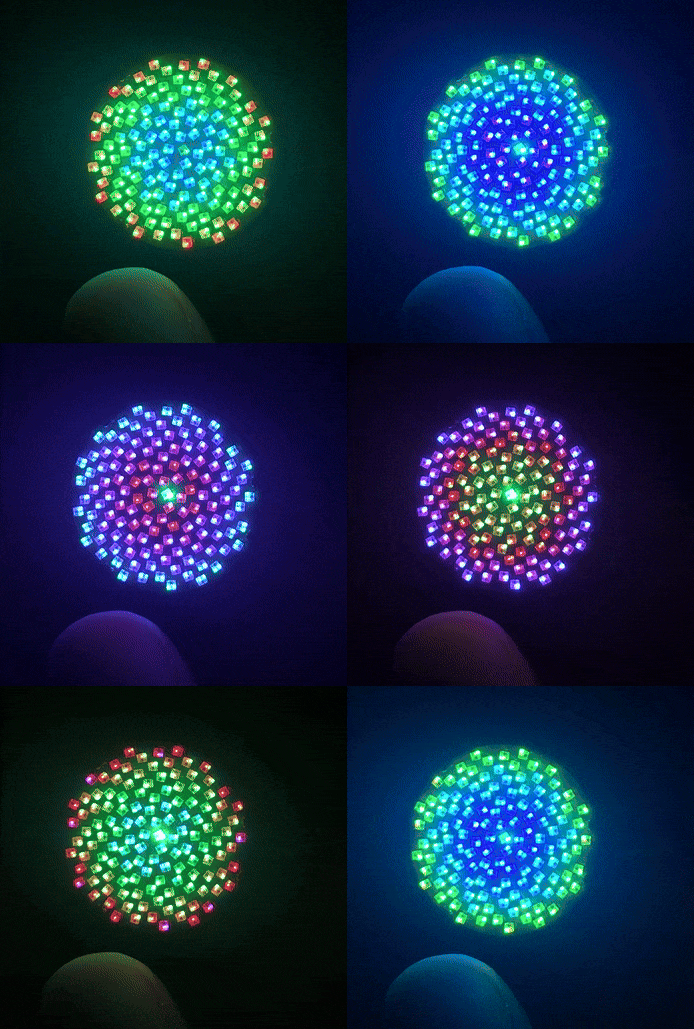
I used function pointers to make a very loose interface that would switch between a few patterns on the fly. There is a bit of weirdness here in that the 40ms timer wound up running about five times more quickly than I’d expected, but this is possibly due to the fact that I am blindly trusting stecman’s (originally commented-out) values for a 40ms timer period. Regardless, this changes the pattern once roughly every five seconds.
void fibonacci(void)
{
    for (uint8_t i = 0; i < NUM_LEDS; ++i)
    {
        wheel((i*2 + lights_index) & 0xFF, lights[fibonacciToPhysical[127-i]]);
    }
}

void pinwheel(void)
{
    for (uint8_t i = 0; i < NUM_LEDS; ++i)
    {
        wheel((i*2 + lights_index) & 0xFF, lights[i]);
    }
}

static void (*patterns[4]) (void) = { pinwheel, horizontalRainbow, fibonacci, verticalRainbow};
static uint8_t patternIndex = 0;
static uint16_t timer2_counter = 0;

void timer2_overflow_interrupt(void) __interrupt (ITC_IRQ_TIM2_OVF)
{
    patterns[patternIndex]();

    lights_index++; // naturally overflows at 255; sue me

    ++timer2_counter;
    // Write to LED strip
...

int main(void)
{
...
    for (;;) {
        if (patternIndex == 3)
        {
            patternIndex = 0;
        } else {
            ++patternIndex;
        }

        // 40ms should go into 1000ms 25 times, but it's five times faster empirically
        // So, uh, MAGIC
        while (timer2_counter <= 625);

        timer2_counter = 0;
    }
}
At this point, I had a fully functional SAO that was able to cycle through a few predefined animations, satisfying the general goal of bringing the insane density of a One-Inch Fibonacci128 to the SAO header.
However, this year’s Hackaday Supercon badge was focused on exploring the possibilities of the I2C interface on the SAO header, with inter-SAO communication being expected. So clearly I had to add an I2C device-mode interface; I’d already allocated the pins for it after all…
Das I2C Interface
After making a careful backup of my working code absolutely no forethought whatsoever, I plunged into adding an I2C interrupt handler, drawing liberally from this Embedded Developer example and consulting this alternate implementation as well. I was also pleasantly surprised by the quality of the STM8 reference manual; I should have just gone to it first since it laid out exactly what I needed to know.
I was able to do very rapid iteration on testing by using a Raspberry Pi Pico with CircuitPython loaded. In fact, the interactivity provided by the CircuitPython interface meant that I didn’t have to pull out a logic analyzer to solve my bugs; I just had to think a little harder.
A fun example of this is the last bug that I found. I was able to read and write to the registers I’d defined in the STM8 just fine, but they didn’t appear to be taking effect - the behavior of the LEDs wasn’t actually changing. Eventually I realized that I was failing to clear the STOPF flag, which signals the end of an I2C transmission. This meant that the STM8 was constantly re-entering the I2C interrupt, waiting for me to clear this flag. It would only take a break when the periodic “40ms” interrupt fired to indicate that it was time to update the WS2812 LEDs… This meant that the code in main() that was supposed to act on this I2C register’s value would never actually run - oops!
static uint8_t I2C_Regs[256] = {0};
static uint8_t I2C_Index = 0;

typedef enum {
    I2C_REGISTER,
    I2C_DATA
} I2C_State_t;

static I2C_State_t I2C_State;


void I2C_interrupt(void) __interrupt (ITC_IRQ_I2C)
{
    uint8_t reg;

    if (I2C->SR1 & I2C_SR1_ADDR) // address match
    {
        reg = I2C->SR1; // clear status regs by reading from them
        reg = I2C->SR3;
        I2C_State = I2C_REGISTER;
        return;
    }

    if (I2C->SR1 & I2C_SR1_RXNE) // receive queue not empty
    {
        if (I2C_State == I2C_REGISTER)
        {
            I2C_Index = I2C->DR;
            I2C_State = I2C_DATA;
        } else {
            I2C_Regs[I2C_Index++] = I2C->DR;
        }

        return;
    }

    if (I2C->SR1 & I2C_SR1_TXE) // transmit queue empty
    {
        I2C->DR = I2C_Regs[I2C_Index++];
        return;
    }

    if (I2C->SR2 & I2C_SR2_AF) // NACK
    {
        I2C->SR2 &= ~I2C_SR2_AF;
    }

    if (I2C->SR1 & I2C_SR1_STOPF) // end of each I2C transaction; has to get cleared or the system hangs up
    {
        reg = I2C->SR1; // need to read SR1
        reg = I2C->CR2; // and write CR2
        I2C->CR2 = reg;
    }
}

// Drawn from https://blog.mark-stevens.co.uk/2015/05/stm8s-i2c-slave-device/
// Interestingly, he ignores the STOPF event interrupt
void I2C_Setup(void)
{
    I2C->CR1 &= ~I2C_CR1_PE; // disable peripheral

    I2C->FREQR = 16;
    I2C->CCRH &= ~I2C_CCRH_FS; // slave mode

    I2C->CCRH &= ~(0 | I2C_CCRH_CCR); // set clock to standard mode (50kHz)
    I2C->CCRL = 0xA0;

    I2C->OARH &= ~I2C_OARH_ADDMODE; // slave mode
    I2C->OARH |= I2C_OARH_ADDCONF; // "must be set by software"
    I2C->OARH &= ~(0 | I2C_OARH_ADD); // clearing extended address bits
    I2C->OARL = 0x37 << 1;

    I2C->TRISER = 17; //MAGIC

    I2C->ITR |= I2C_ITR_ITBUFEN | I2C_ITR_ITEVTEN | I2C_ITR_ITERREN;

    I2C->CR1 |= I2C_CR1_PE; // re-enable peripheral

    I2C->CR2 |= I2C_CR2_ACK; // automatic ACKs
}
Alright, enough C already; what are the actual registers that I’m exposing?
I’m so glad you asked!
The first register I added was one that would set the animation mode. I had already made a few animations, but I also wanted to have a mode that would cycle through each of them and one that would force the STM8 to relinquish control of the LEDs altogether so that the host badge could drive them directly; I wound up bodge-wiring this LED input pin to the GPIO2 pad so that a badge could take control purely through software (I also wired the SWIM pin to GPIO1 so that I could reflash these live without needing to solder to the PD5 solder pad).
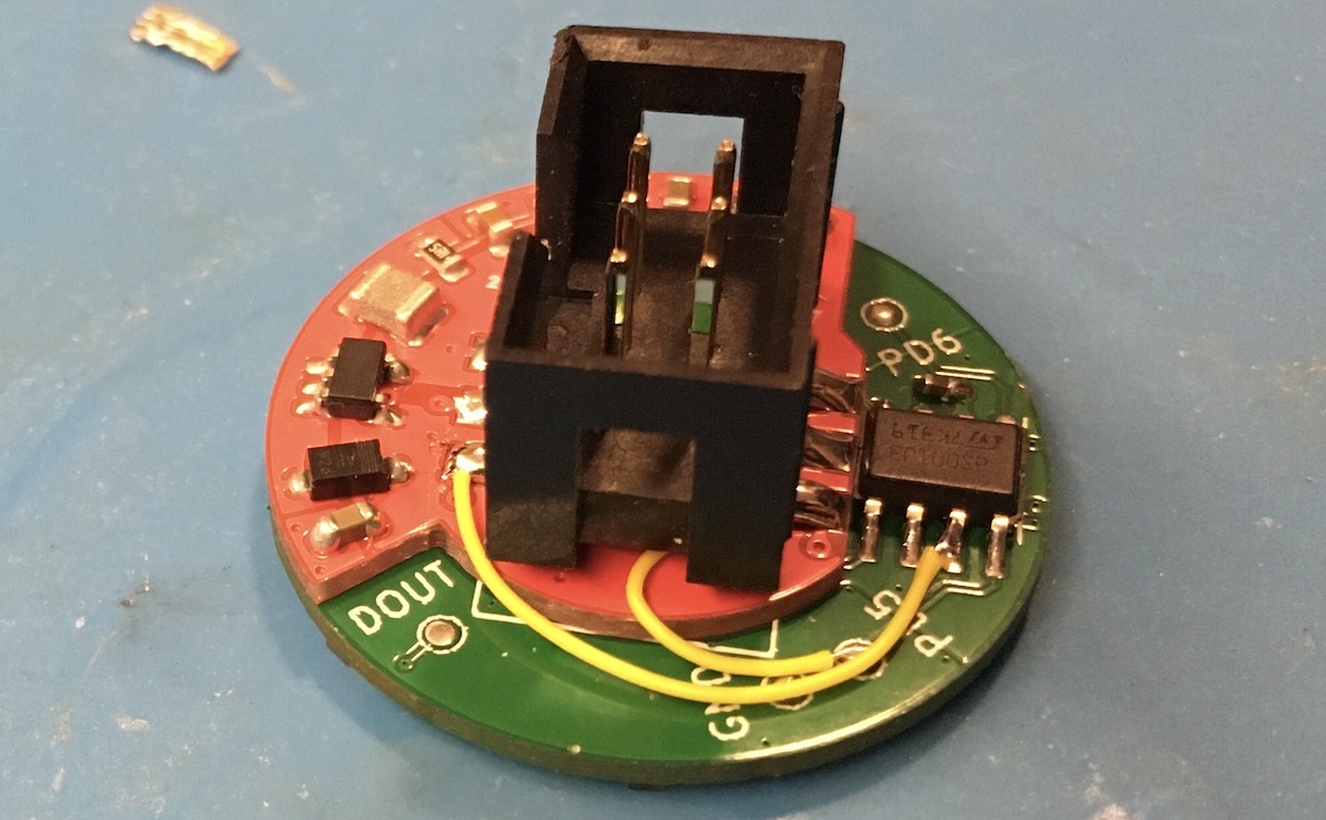
After implementing this, however, I realized that it would be neat to be able to stream the display contents in over I2C, so I rearranged the registers so that the first 128 registers would serve as a rather decimated framebuffer, with each byte forming a 3R:3G:2B-encoded pixel value. This loses a lot of precision, but it should still have enough granularity for you to write your name…
I added this as another display mode and found out while testing it that my Pico’s I2C interface was so slow that you could actually see the LEDs updating live, each new value advancing along the serpentine LED data path. This was another unexpected feature - it’s actually a live-updating framebuffer! Probably increasing the Pi Pico’s I2C clock speed would alleviate that a little bit.
I also wanted to add a way to change the brightness, initially because I was worried that people would want to make it brighter than my default divisor of 12 (I’ve never been brave enough to divide by less than 5; you might start melting people’s faces at that point…). However, after taking an example board in to work, I realized that it might be just as important to be able to turn the brightness down, whether to spare your batteries or your eyeballs.
I made a quick little subpage called otterwork on here for I2C documentation for the recipients of my extra SAOs, but the simplest documentation is the quick header comment that I threw in the source code. I used I2C address 0x37 (0x6E if you’re counting the R/W bit).
// -------------
// I2C Registers
// -------------
//
// 0-127 - [3R:3G:2B] encoding of LEDs 0-127
//
// 128 - LED pattern
//       - 0: Pinwheel
//       - 1: Horizontally-scrolling rainbow
//       - 2: Bullseye pattern
//       - 3: Vertically-scrolling rainbow
//       - 4: [3R:3G:2B] encoded values from I2C; updating live
//       - 5: Cycle through patterns 0-3
//       - 6: Set LED driver pin high-Z so you can drive it from GPIO2
// 129 - LED brightness divisor (wouldn't recommend going above 5; 12 is easy enough on the eyes)
I’m not going to paste all the source code inline on this page, but I do have all the code and build files linked on the otterwork page.
An interesting aside - I did all the software development on an Arch Linux desktop, which made it very easy to pull down copies of SDCC and stm8flash for programming. However, I wanted to be able to program these on the go and at Supercon, which meant that I needed to be able to build the firmware and program the boards on a Mac laptop.
To my surprise, I was very easily able to pull down SCons and SDCC from homebrew, as well as build stm8flash from source, on both an Apple Silicon laptop and an Intel-based Hackintosh laptop (yes, I like to live dangerously). People keep telling me that SCons is obscure and terrible, but I’ve only had progressively better experiences with it after starting out trying to compile the gem5 computer architecture simulation system…
Sidequest - Boxes
I wound up with all four (recall that out of the five boards I’d ordered, I’d already given one to a friend who attended Supercon 7) boards fully assembled with time to spare, so it was clearly time for a little scope creep. I definitely didn’t want to come home with more than one of these boards left, but I figured that it would be a nice idea to provide the unwitting recipients of these boards with a link to the documentation for the I2C interface.
A normal person would print out a QR code or link on a piece of paper and drop it in an ESD bag, but being normal is clearly overrated. I decided it would be a fun exercise to borrow a laser cutter and make little boxes with QR codes to the otterwork page etched onto the back.
I was able to leverage the parametric templates at templatemaker.nl to get close to what I wanted. Then I hand-merged the resultant SVGs until I was able to define a neat 2” (50mm) square box with an inset that would hold the SAO box header. The big problem with this design is that I assumed a negligible material thickness, but I hadn’t brought any suitable cardstock or thin cardboard with me, so I had to scrounge around for cardboard.
What I eventually found was your standard double-ply corrugated cardboard, which is wonderfully robust but also decidedly non-negligible in thickness. It took a few runs with the laser cutter to get the cut depth and etch power dialed in, but the design needed to change considerably in order to go together at all.
I wound up having to connect the dots from the back with a hobby knife and remove several tabs to get anything to connect. I also used a not insignificant amount of superglue to hold the box tabs in place (and of course to plasticize half a finger due to underestimating superglue’s flesh-seeking proclivities)…
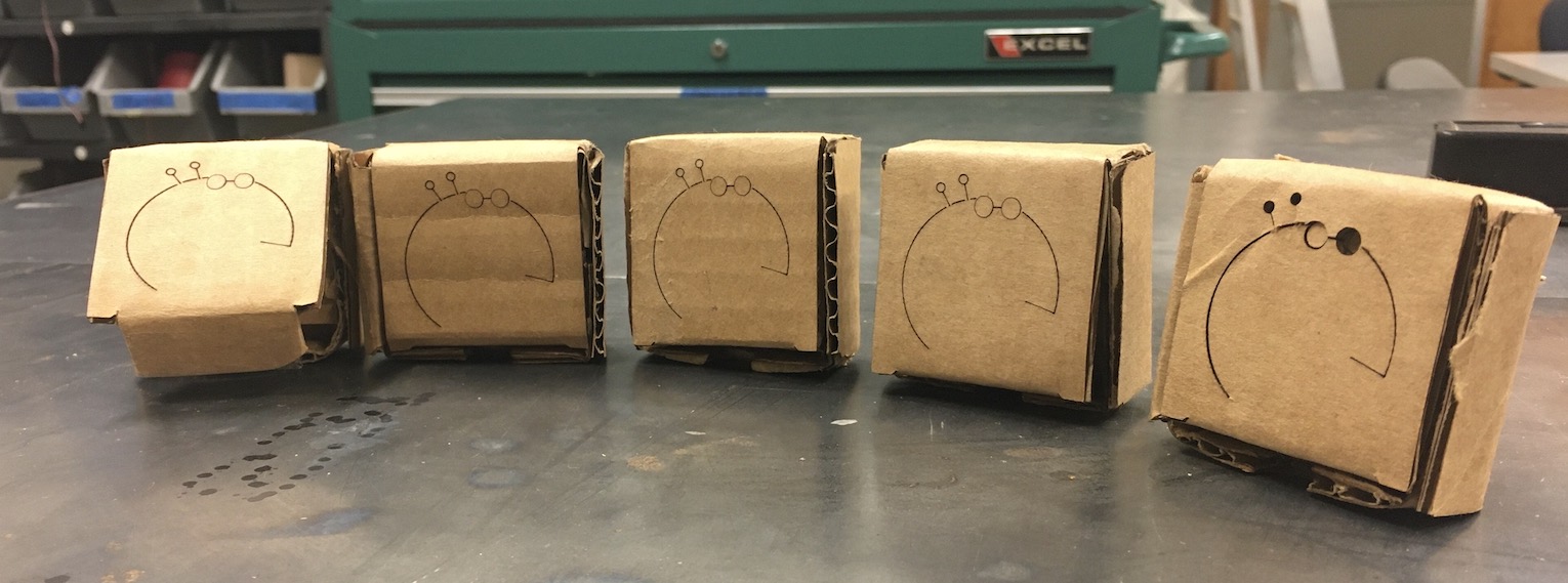
The results were mixed, to say the least. I somehow didn’t manage to get a picture of it, but I wound up coloring in the QR codes on the back of two of the boxes with a fine-tipped pen. On another box, I started trying to color them in with a Sharpie marker and gave up due to the ink bleeding; I just wrote the URL by hand on that one.
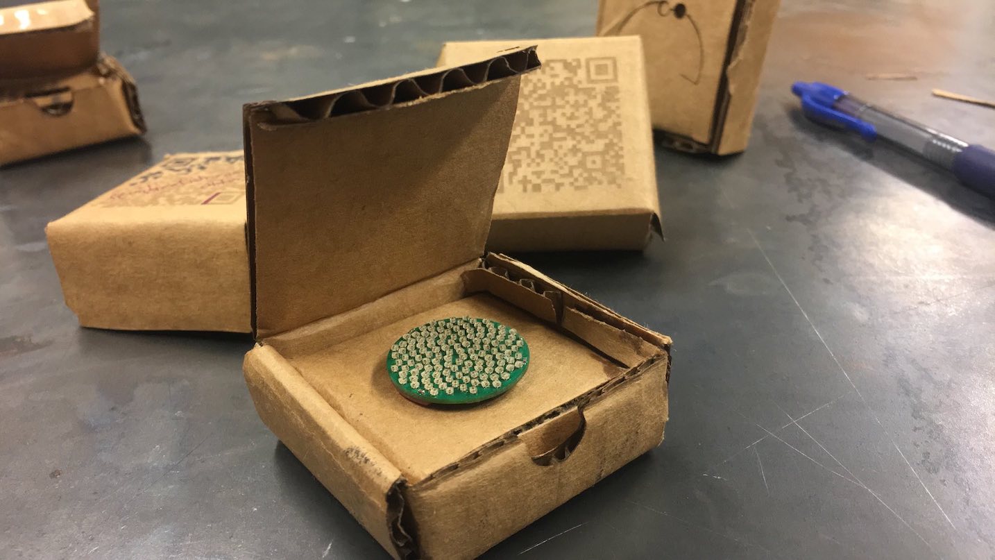
On the other hand, maybe my expectations were misplaced - I have been told that people “[love] the handcraftedness of those,” so maybe I just needed to think more rustic. If there is a next time, I’ll try to use some actual cardstock and use a normal printer to put the QR code on…
Supercon
All hassle aside, I finally arrived at Supercon on Friday morning, and it was absolutely amazing. You walk in the door and absolute strangers hand you bags of PCBs and point you towards the food and soldering irons; it’s time to start hacking! I had an awesome time meeting people whose projects I’d read about in detail on Hackaday and elsewhere, churning away on modifications to my badge and its SAOs, and seeing what weird and wonderful projects others had brought to the convention.
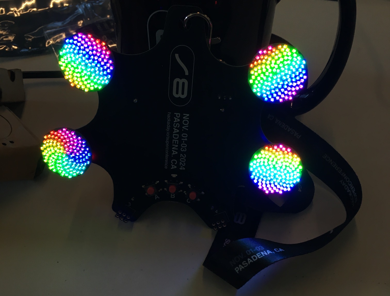
Here is my badge with four of these LED boards connected; they managed to cause the badge’s integrated Pi Pico W to brown out and power cycle immediately.
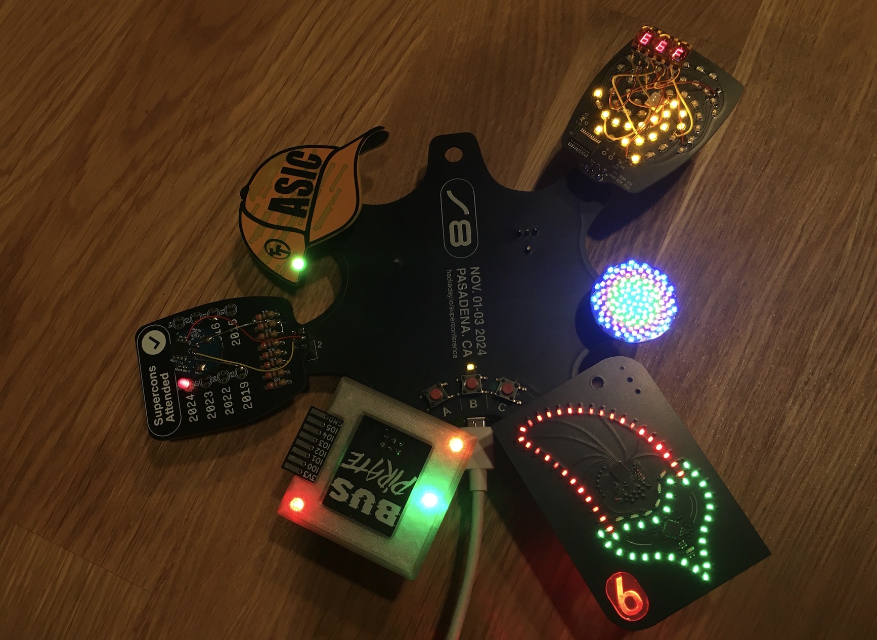
Here’s my badge after two days of receiving SAOs and tweaking firmware. The red 7-segment display is an HP 5082-7433 common-cathode bubble display, wired up in parallel with the yellow LEDs of the Petal Matrix SAO via 20-Ohm 0603 resistors. It is displaying the ambient temperature as measured by the little PCB deadbugged onto the “Supercons Attended” SAO. That PCB is an I2C-connected LM75A temperature sensor that originally was glued to the hard drive on an A1208 (2006 17” iMac).
The Circuit Graver
As I mentioned earlier, one of the big highlights of Supercon for me was meeting people about whose projects I’d read in detail online. A perfect example is Zach Fredin, maker of the Circuit Graver and a few other projects I remembered seeing on Hackaday.
On Saturday evening, I was sitting in the badge hacking area working on getting the petal matrix to drive my deadbugged bubble display when Zach came by.
“Is anybody sitting here?”
“No; feel free”
“Do you mind if I set up a machine on the table here? It shouldn’t move too much”
“Of course not; go ahead….wait, is this that drag-knife 4/4 PCB mill????”
(Zach was already signed up to give a talk about his novel CNC PCB-making device which isolates nets by dragging an extremely sharp cutter through the top layer of the PCB itself; check out his hackaday.io page or Hackaday front-page article for more details.)
I wasn’t able to attend his talk because I’d signed myself up to give a Lightning Talk, which happened to be scheduled at the same time. However, we spent a few hours at the badge hacking tables hanging out, sharing tools and stories, and yelling at our respective laptops.
After the insane dinner line for tacos died down, we wound up trying to make one of my boost-converter dorkopods on the Graver. Unfortunately, some combination of KiCad’s SVG export, Inkscape on macOS, and the fact that my board was very much designed for mask-based production rather than subtractive machining meant that the outputs didn’t quite turn out the way we’d hoped.
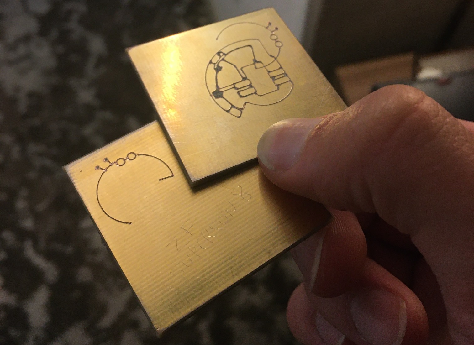
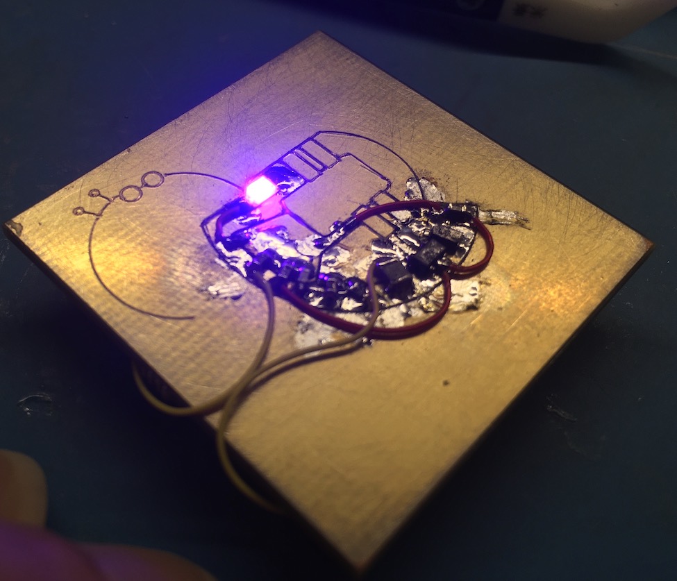
On the other hand, the Graver produced this board in a matter of minutes - far faster than any CNC PCB mill I’ve seen, and skipping all the scary chemistry that comes with etching your own boards at home… Since the minimum feature size is now a single blade’s kerf width, you can feasibly prototype with parts as small as QFN without needing to order commercial PCBs.
I definitely want to build a Circuit Graver, but I’m not sure I trust my 3D printer to produce true enough parts.
I threw a boost converter’s worth of parts on my next Digikey order (which somehow always happens sooner than I expect) and managed to get it working properly. I had to do a lot of cleanup with a razor knife because we didn’t quite have the cut depth set correctly, and there was a weird issue with parsing the KiCad paths where the Graver would try to backtrack on each trace.
This meant that sometimes we’d get double cuts and other times it would just kind of chew up the board. The Graver did much better with sane single-line inputs as opposed to my crazy polygons, which is totally fair. I imagine that some mucking around with the vector outputs in software could resolve most of the problems we had here.
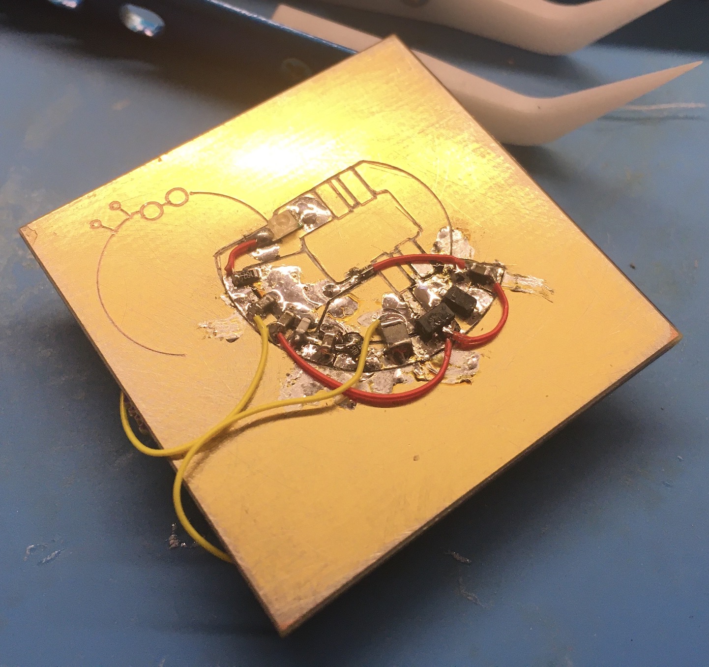
We also managed to lose a trace, so I got to improvise when it came to mounting the LED. Incidentally, that LED is pulled off what used to be the number pad of the rotary dial keyboard.
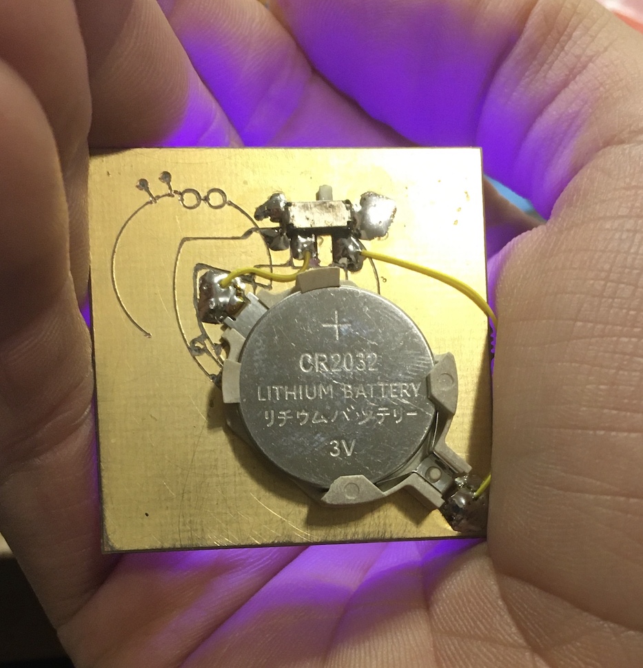
My phone over-exposes the heck out of it, but it does make a nice purple light (and it is indeed a stable 5V). The back of the board has a test run where we set the Graver’s cut depth a little too deep, so I used part of that wonky layout to mount a switch and 3V battery holder for fun.
Let me end this section with possibly my favorite quote from this wild weekend:
[Squidgeefish], your ground pours are unhinged
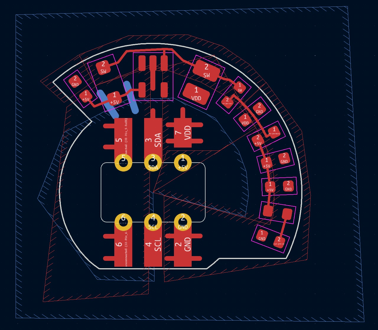
…guilty as charged. In fact, it’s even worse than it looks - I had tiny arcs defined on the User.Eco1 and User.Eco2 layers that I would promote to the F.Cu and B.Cu layers to get just a little more clearance on the pours and then drop them back down.
In retrospect, I did almost all the routing on this board using pours. It would have been easier/better for the Circuit Graver if I’d just redrawn it as a few vectors that indicated the boundaries of the pours…
Future Developments
So you may be wondering how to get your hands on one of these, whether because you want to make new patterns for it or you just want to sear some retinas. Since this design is pretty much an exact clone of Jason’s board (and since I’m not exactly looking to get into the hardware production business), I went into Supercon figuring that I’d only be trading these or giving them away, but that I might be able to release design files if Jason was fine with it.
I was hoping that I’d be able to meet him in person and we’d be able to hash out exactly what he wanted to do, but he wasn’t able to make it to Supercon this year.
However, if you walk around Supercon with what may be the densest/brightest RGB SAO yet, it is hard to escape attention, and I soon wound up talking to the LED-bedazzled Anthony of Sun and Moon Couture, who it turns out knows Jason quite well and was very eager to facilitate conversation in order to get more Fibonacci designs out there.
After a few rounds of email alias juggling (technically started before Supercon, but not fully successful until I met Anthony), Jason and I managed to establish two-way radio contact and have agreed that it makes sense not to open-source my hardware design files since this is absolutely his domain and he has lots of stock already assembled.
However, we’re working on making a daughterboard that will allow the usage of his existing One-Inch Fibonacci128 boards as SAOs, potentially with a SAMD21 running the show rather than an STM8. This should allow for the classic ColorWaves patterns and capacitive interactivity characteristic of an Evil Genius Labs product.
So no hardware release for now, but there are options in the pipeline. I’m also considering respinning my design to use both internal layers and integrate the boost converter onto the main PCB; if I do that, I’ll definitely bring several to the next Supercon to hand out…
