Cloning 5n4ck3y-7r
Background
I went to DEF CON 31 this year and was lucky enough to pick up one of the AND!XOR 5n4ck3y-7r (Snackey Jr) badges, which was part of their CTF. It has a variety of delightful challenges onboard, ranging from hardware sniffing to hash cracking to graph theory to physical disassembly of the badge. A friend from work and I worked through all the challenges on the badge and wound up as high as third place on the leaderboard at one point.
My friend got his badge first, and we spent a while working on it before coming back later in the day to stand in line to get mine (for those unfamiliar, the AND!XOR team has a modified vending machine, named 5n4ck3y (Snackey); to get one of their badges, you need to solve a few challenges to get a code to punch in. Very cool, but also very prone to queueing problems…).
Of course, the first thing we did was tear it apart to see what was going on under the intriguing laser-cut wood faceplate, as well as making a backup of its firmware for if we managed to screw it up (pro tip - the two button footprints over the crystal are RUN and then BOOTSEL as you go up, but you can force the badge into the recovery bootloader by shorting pins 1 and 4 of the SPI flash on the back of the badge).
![]()
This is a relatively straightforward design based around an RP2040 microcontroller, with a 3.3V LDO regulator and some ESD protection for the USB data lines. Given how long the line was for the vending machine, we wondered if it would be possible to flash the firmware to a generic RP2040 development board like a Raspberry Pi Pico that I happened to have in my backpack.
After standing in line for about an hour and getting the 5th-to-last badge on Friday, we asked Hyr0n if it would be possible to do this but were told that it would require a bit of extra hardware to get the firmware working properly on the Pico. Of course, rather than being appropriately discouraged, we took this as a challenge…
As a note for those who may still be working through the challenges on your own 5n4ck3y-7r badge, there will be mild spoilers for some of the challenges. Proceed at your own risk!
Flash Memory
The first issue for us was that the Raspberry Pi Pico has a 2MB SPI flash chip, as opposed to the 16MB SPI flash chip used on the badge. Looking at our firmware dump, we found that the “unprovisioned” firmware from the badge didn’t use any flash past the 2MB mark. However, the RP2040’s UF2 bootloader isn’t smart enough to notice that, and so if you feed it a 16MB image with a 2MB flash chip, it will overwrite the 2MB flash chip eight times as it loops back around… Whoops!
We avoided this by truncating our firmware dump to 2MB and copying that over with picotool. This allowed us to connect to the serial console properly and see the SNACKEYJR mass-storage device pop up, which was very promising.
Yes, all the commands are emojis. Yes, we all had a wonderful time copy-pasting them around…
BENDER $ help
help: command not found
Type ❓ for list of available commands. Yeah nerds, the emoji...LOLZ!

BENDER $ ❓
❓	❔	🆑	🌈	🌾	🍆	🍎	🍖	🍘	🍜
🍟	🍧	🍰	🍶	🍾	🏥	💌	💩	💻	📜
🔪	😋	🙀	🚩	🤖	🥃	🥓	🥔	🥕	🥙
🥜	🥣	🥧	🥩	🦆	🧀	🧁	🧠	🧮

BENDER $ 🧀
Badge challenges are not yet activated, check RTFM.MD!!!
Once you get a badge from the vending machine, you need to copy some files over to it and then “activate” or “provision” it to activate all the onboard challenges. Taking another copy of the firmware after doing this, we found that it was using just short of 4MB, which wouldn’t fit on the Raspberry Pi Pico’s 2MB SPI flash.
We wandered over to the Hardware Hacking Village and dug through the piles of circuit boards that were explicitly labelled as “for parts,” laid out so that people would be able to pull components off to build or repair whatever they needed. I wound up finding a laptop marked as “Very dead; you won’t be able to fix it,” and pulled the motherboard out to find a Winbond 25Q64FVSIG 8MB SPI flash chip. (Almost all SPI flash shares the same rough pinout, and the 25* prefix typically goes with SPI flash, so I wasn’t just blindly guessing at which chips’ part numbers should be looked up).
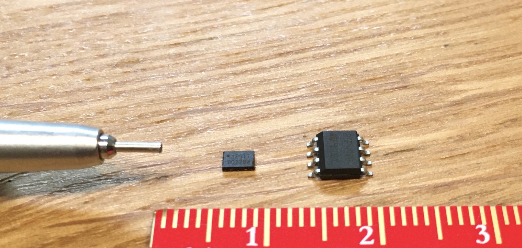
We were able to get this chip desoldered there, but there was a bit of a snag - the physical footprint of this SOIC-8 flash chip was way larger than the USON-8 footprint of the SPI flash on the Raspberry Pi Pico, which meant that installing it on the Pico would take more than just a quick fly-by with a hot air wand. The following picture shows the relative sizes along with an absolutely gigantic 0.5mm mechanical pencil tip for scale.
We wound up over in the Embedded Systems Village, where there was an excellent hands-on lab in the back corner. While their main goal was educating people about on-board protocols, chip glitching, desoldering chips, and obtaining flash reads, they graciously allowed us to borrow one of their hot-air soldering stations and the accompanying magnification camera (which was, incidentally, projecting the active workspace onto the wall - so if you were there on Saturday afternoon, you may have seen me soldering this).
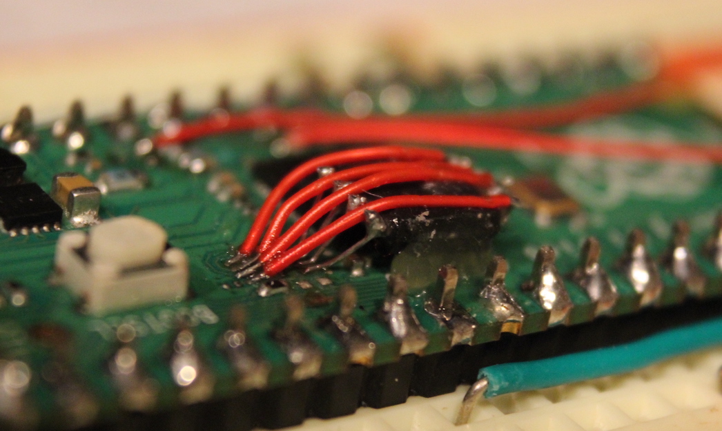
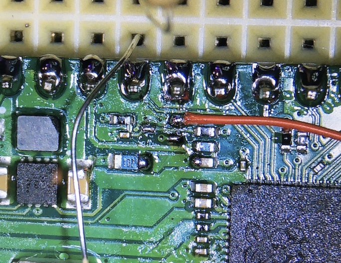
I wound up turning the SOIC-8 flash chip upside down and hot-gluing it to the top of the RP2040 so that I could run small (30AWG) jumper wires to its leads. This process is known as “deadbugging” due to the victim chip’s resemblance to a bug lying on its back with all the legs waving in the air…
This was moderately tedious, but with good flux, excellent magnification, a nice pair of tweezers, and very steady hands, I was able to get it soldered up properly, with no short circuits.
If you look closely, you can see that the close pins were done with un-insulated wire going essentially straight up to the SOIC-8 pins. The other set of pins was connected using roughly 1cm long pieces of 30AWG wire. It was very helpful here that most SPI flash packages, regardless of footprint size, share the same ordering of signals. This meant that I could make this a one-to-one mapping rather than having to worry about wires crossing over each other.
Truncating the “provisioned” firmware again to avoid an overwrite, we copied it onto our new SPI flash in a painfully slow process. However, it did work and we were greeted by a fully-activated badge.
Thermistor
A pair of challenges on the badge rely on a thermistor, a device whose resistance changes as a function of temperature. However, my bare-bones Pico board didn’t have this installed at all, and so it was reading an infinite resistance. This led it to think that it was very warm indeed, and it began spamming the serial console with the success message intended to notify you that you’d reached the high-temperature threshold.
This is kinda awkward, so we decided this would be the first thing we’d implement on our 5n4ck3y-7r knockoff.
I figured that we could probably emulate the thermistor with a voltage divider using a pair of resistors, but we weren’t sure what ratio we needed. Using a multimeter in continuity mode, we found that pins GPIO_7 and GPIO_28/ADC2 were connected to either side of this thermistor.
Monitoring the voltage across the thermistor revealed that it was only being activated periodically, so we turned to the CircuitPython REPL for answers (connect to the first rather than second serial port presented by the badge and then hit ^C to get the option for the REPL):
# Code done running.
# Auto-reload is on. Simply save files over USB to run them or enter REPL to disable.
#
# Press any key to enter the REPL. Use CTRL-D to reload.
#
# Adafruit CircuitPython 8.0.5-dirty on 2023-07-23; AND!XOR DC31 Roberto with rp2040
>>> import roberto
>>> import digitalio
>>> dir(roberto)
['__class__', '__name__', 'const', '__file__', ...
'THRESHOLD_THERM_COLD', 'THRESHOLD_THERM_HOT', ...
'therm_out_pin', 'therm_in_pin', ...
'get_voltage', ...]
>>> roberto.therm_in_pin
<AnalogIn>
>>> roberto.therm_out_pin
<DigitalInOut>
>>> roberto.get_voltage(roberto.therm_in_pin)
0.0281982
>>> roberto.therm_out_pin.direction = digitalio.Direction.OUTPUT
>>> roberto.therm_out_pin.value = True
>>> roberto.get_voltage(roberto.therm_in_pin)
1.07742
>>>
Looking at the various fields of the roberto object using dir(), we identified THERM_OUT and THERM_IN pins, which we figured mapped to the digital and analog pins respectively. This was validated by checking their types with the REPL (note the <AnalogIn> and <DigitalInOut> types above). Turning on the THERM_OUT pin allowed us to get a non-zero reading back from the internal get_voltage() command, about 1.1V.
Since the RP2040 is a 3.3V-based microcontroller, we needed a roughly 2:1 voltage divider. Using the resistors I had on hand, we threw a 4.7kΩ resistor between GPIO7 and ADC2 and a 2.2kΩ resistor from ADC2 to ground, giving us a bit less than 1.1V at ADC2.
This successfully stopped the aggressive printing of the high-temperature announcement and revealed an easy way for us (or anybody with a real badge, I suppose) to trigger the temperature thresholds:
- Coerce
ADC2low (remove the high-side resistor) to emulate infinite resistance, triggering the high-temperature threshold - Coerce
ADC2high (remove the low-side resistor) to emulate no resistance, triggering the low-temperature threshold
| RP2040 pin | 5n4ck3y-7r location | 5n4ck3y-7r usage |
|---|---|---|
GPIO7 |
left side of thermistor | Drive high to read |
ADC2 |
right side of thermistor | Analog input |
Coin cell
A different challenge has you insert a coin cell battery into a slot in the badge.
The positive and negative terminals go to RP2040 pins ADC3 and GPIO23, respectively. Unfortunately for our Pico-porting plans, the designers of the Raspberry Pi Pico did not route either of these pins out for general use.
ADC3 is run through a MOSFET Q1 to a voltage divider monitoring the VSYS rail.
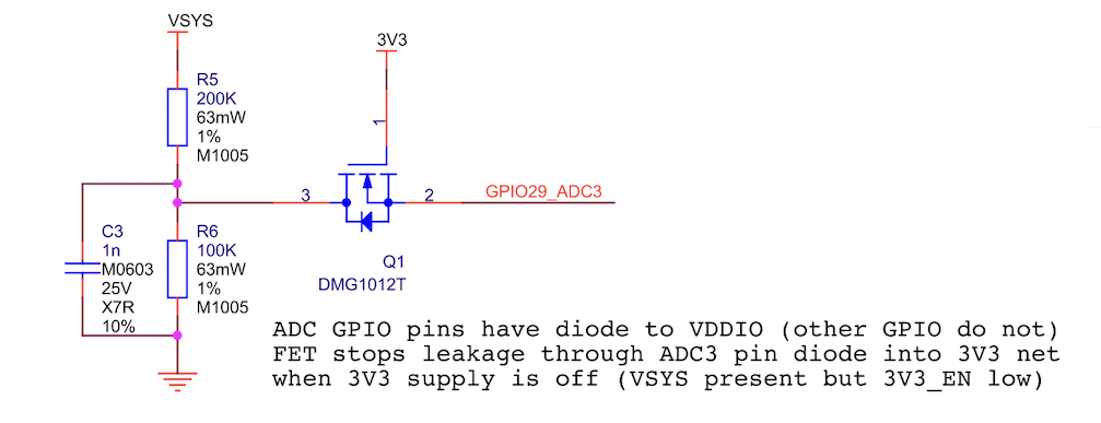
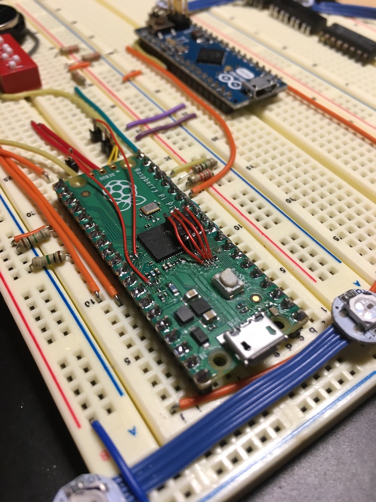
I desoldered the MOSFET and soldered a wire to pin 2 of Q1, allowing me to use ADC3 directly. Fun fact: I was able to do this with a Pinecil soldering iron at one of the 5n4ck3y tables. USB-C PD battery banks are absolutely amazing.
Next up is GPIO23, which the designers of the Pico routed over to a pin which controls the efficiency of the switching 3.3V regulator. Luckily for me, they also routed it to test point TP4 on the bottom of the Pico, so I could solder on there rather than committing further acts of board mutilation (for now, that is).
After playing with this in the REPL, I couldn’t find a quick way to bypass the check, so I just hooked up an actual 3V source (a different badge with some jumper wires jammed in its battery springs).
Around this time, my 5n4ck3y-7r badge stopped booting completely, with a direct short from GPIO23 to IOVDD, which not only made tracing it out with a multimeter more confusing but also meant that I was down a badge…
Somehow, I’d managed to fry part of the RP2040, and so I had to wait until I got home to replace the RP2040. However, I could still proceed with static analysis of the board’s layout, with the hope that I could make my Pico knock-off fully compatible with the original challenges. Now making a 5n4ck3y-7r knockoff wasn’t just a fun side project; it was the only way for me to continue to get my 5n4ck3y-7r fix!
| RP2040 pin | 5n4ck3y-7r location | 5n4ck3y-7r usage |
|---|---|---|
ADC3 |
Coin cell positive terminal | coin_in_pin |
GPIO23 |
Coin cell negative terminal | coin_out_pin |
UART
There is a pair of challenges that has you connect a 3.3V UART adapter to the upper pair of screws, by the lanyard holes, and interact with the badge over a serial connection. The left hole is GPIO9, used by the RP2040 to receive, and the right hole is GPIO8, used by the RP2040 to transmit.
There’s not a whole lot more to say here; I wired it up and it worked once I set my serial adapter to the right voltage and baud rate.
| RP2040 pin | 5n4ck3y-7r location | 5n4ck3y-7r usage |
|---|---|---|
GPIO9 |
Upper left screw hole | RP2040 RX |
GPIO8 |
Upper right screw hole | RP2040 TX |
Jumper wire
A challenge has you short the other two screw holes together. The left and right screw holes are ADC1 and GPIO12, respectively.
Note that the silkscreen says that there’s a 2kΩ resistor between GPIO12 and its screw hole. Hyr0n informed me that this is in fact a lie; all the resistors on the board are 5kΩ. Unfortunately for him, this also included the resistors in series with the USB data lines, and so he had to replace them with tiny 0402 27Ω resistors on the hundreds of badges that had been ordered with the incorrect values…
| RP2040 pin | 5n4ck3y-7r location | 5n4ck3y-7r usage |
|---|---|---|
ADC1 |
Lower left screw hole | connect_in_pin |
GPIO12 |
Lower right screw hole | connect_out_pin |
Cut Trace
You have to cut a trace for one of the challenges. I’ve heard from other people that you can fake this out by shorting it one way or the other, and I’m sure that’s true. I like playing with knives, so I just went and cut it…
There’s another one of those fake 2kΩ resistors that’s actually a 5kΩ resistor on the GPIO11 side of things. As you’d expect, it works just fine with 2kΩ resistors rather than 5kΩ ones for this sort of safety current-limiting application. I think they probably switched to using as many 5kΩs as they could to save on costs - you often save on parts when you buy them in bulk, and the places that do PCB component assembly probably also charge more if you have lots of different components for them to install.
| RP2040 pin | 5n4ck3y-7r location | 5n4ck3y-7r usage |
|---|---|---|
GPIO11 |
Upper side of cut point | cut_out_pin |
ADC0 |
Lower side of cut point | cut_in_pin |
Capacitive touch
There are three capacitive touch pads on the board. Two are on the back, and if you hold them both (or if you sneeze in just the wrong way), they’ll trigger the badge to run a USB Rubber Ducky script that opens https://www.andnxor.com, which is fun the first few times. Capacitive touch is notoriously finnicky, and it’s quite impressive how consistently it’s working on the badge with just a 5kΩ drainage resistor to ground. Usually you’d have custom hardware like a TTP223, but the RP2040 is (mostly) up to the task.
For those wondering, the basic theory of operation is that the RP2040 will load up the pin and then watch how quickly it drains down to 0V. If a meatbag capacitive load like a finger is touching the pad, it will take longer for that pad’s voltage to decay down to 0V. With sufficiently precise timers, you can figure out whether there is a capacitive load connected, but it does take a bit of fine-tuning.
I pinned these out as well and actually got them working-ish on a smaller breadboard with 1MΩ drainage resistors, but I haven’t gotten it to work on my larger breadboard at home. This could be due to the fact that I’m using 1MΩ resistors (like the silkscreen says) rather than 5kΩ resistors (like the firmware is actually tuned for), or it could have to do with humidity or breadboard capacitance or the phase of the moon…
In any case, the one badge challenge that uses them seems to trigger automatically, so I haven’t tried too hard to get them working again.
| RP2040 pin | 5n4ck3y-7r location | 5n4ck3y-7r usage |
|---|---|---|
GPIO14 |
Touch pad under CTFd text | Cap 1 |
GPIO18 |
Touch pad under SPI flash | Cap 2 |
GPIO19 |
Touch pad on front of board | Cap 3 |
Blinkenlights
Alright, so at this point you have all you need in electrical terms to turn an unsuspecting Raspberry Pi Pico into a 5n4ck3y-7r knockoff and get its internal progress counter to 100%. But we’re missing the glorious blinky lights that are the very heart and soul of a modern conference badge.
The individually-addressable LEDs on 5n4ck3y-7r are 6-pin units, and their pinout looked like it matched APA102 “DotStar” LEDs, which use a SPI-like protocol, as described in excellent detail over at cpldcpu’s APA102 page.
The data line for these APA102s is GPIO24, which the Raspberry Pi Pico designers ran to a voltage divider for sensing VBUS. I removed both resistors in this divider (R1 and R10) and soldered directly to the GPIO24 net.
The clock line is GPIO25, which routes on the Pico both to TP5 and to the built-in LED. I would have liked to keep the LED in place, but investigating with a logic analyzer indicated that it was messing with the clock signal, which was completely unacceptable, so the LED had to go. Luckily, I’d already soldered to TP5 on the bottom of the board, so this wasn’t too bad.
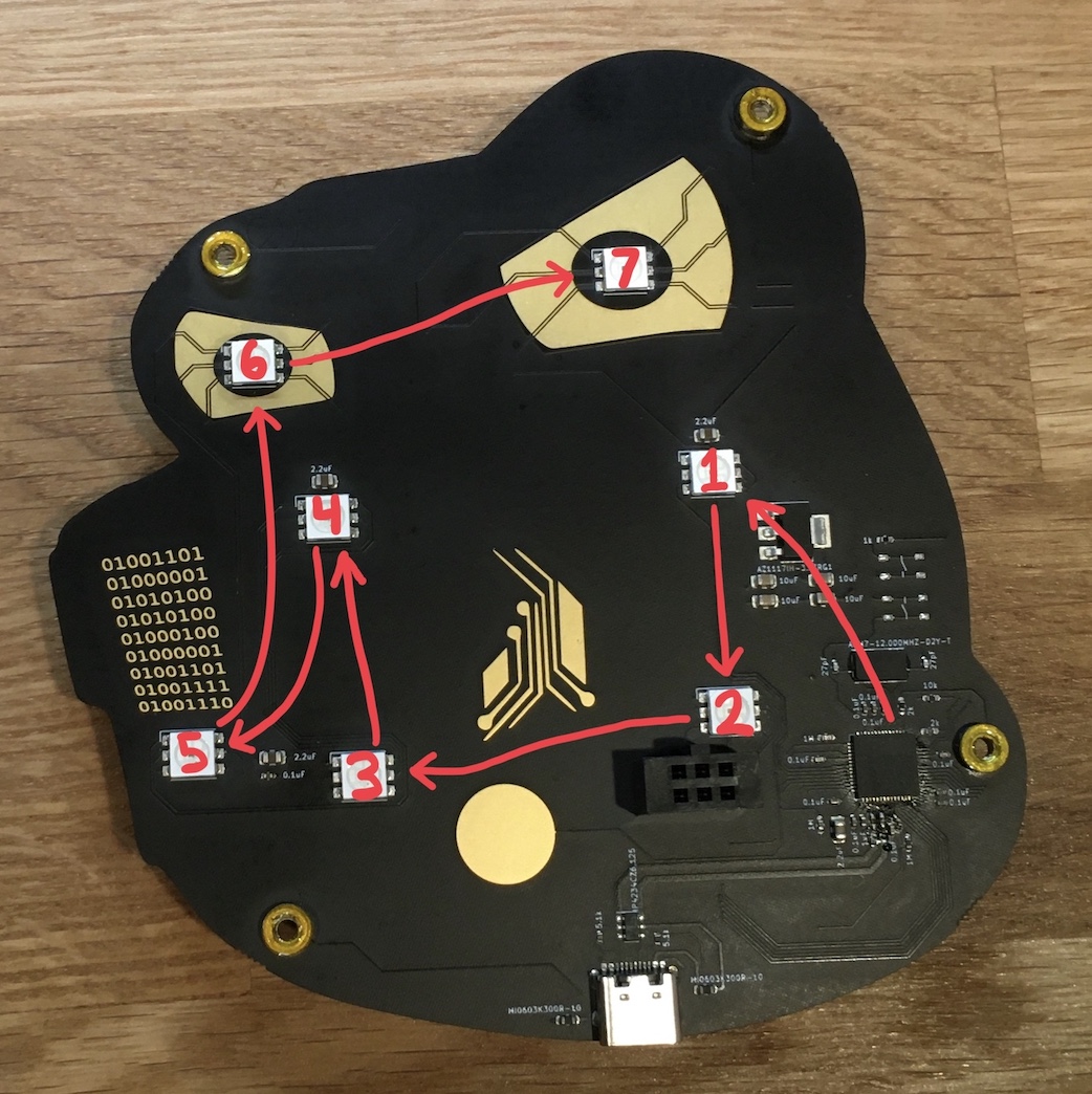
The actual APA102 ordering on the PCB is a bit confusing, and the traces are even more confusing. I’m not going to say that this was auto-routed after the aesthetic concerns were handled, but it certainly threw me for a loop while tracing it out.
| RP2040 pin | 5n4ck3y-7r location | 5n4ck3y-7r usage |
|---|---|---|
GPIO24 |
APA102 by LDO | APA102 data |
GPIO25 |
APA102 by LDO | APA102 clock |
Unfortunately, I only had WS2812s on hand that I’d literally pulled out of a garbage bin. I suspect the previous owner overheated most of them while trying to solder them into a chain with large single-core wire and pitched the whole mess after they failed to work properly. A friend and I managed to cull most of the dead/melted ones out of the lot, and the working ones have been hiding in a dark corner of the parts bin ever since.
While some might just wait for shipping on a nice string of APA102s, that kind of goes against the scrappy stick-some-junk-together nature of this whole project. So I grabbed an Arduino Micro out of the parts bin and wrote a quick and dirty program that would receive the APA102 transmissions from the RP2040 and translate them into the right format for the WS2812s.
Astute readers might notice that the LED corresponding to the “left eye” appears a bit greener than its companion at the end of the string. This isn’t a problem with the decoding; rather, it’s an issue with the actual red LED phosphor in that WS2812 being just a bit dimmer than any of the others. I discovered this after wiring everything up; it can probably be chalked up to over-heating by the previous owner and arguably should be replaced. I think it adds character…
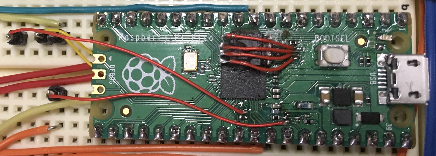
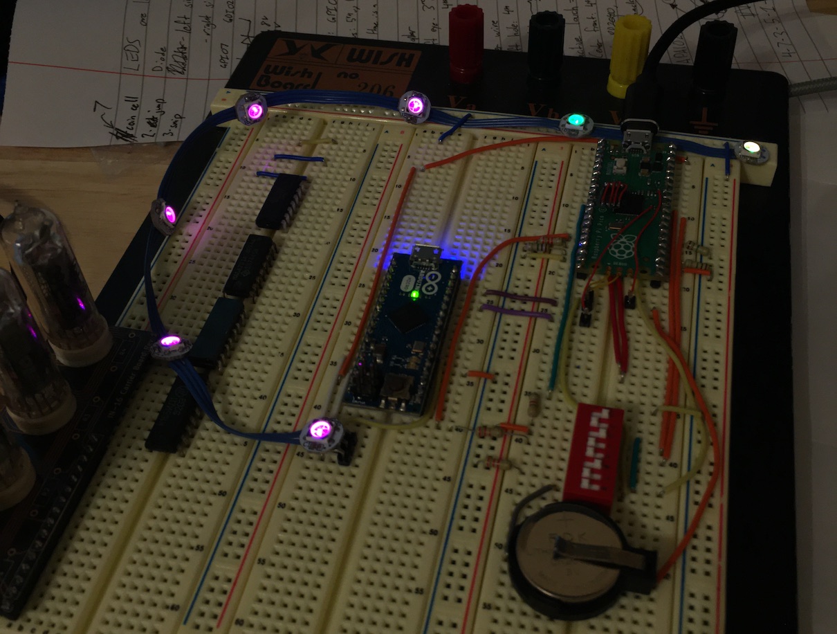
Pictures
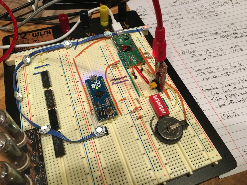
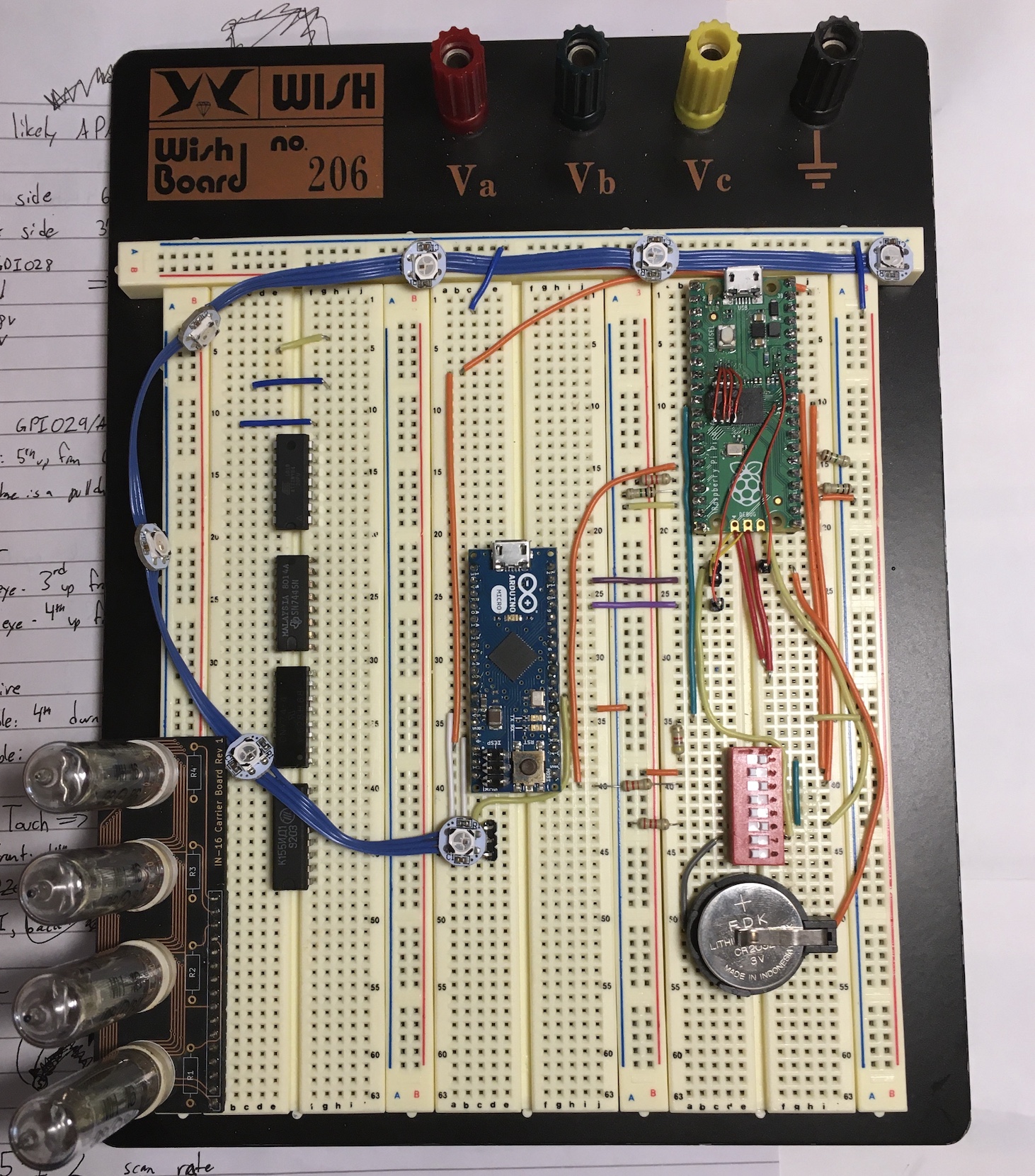
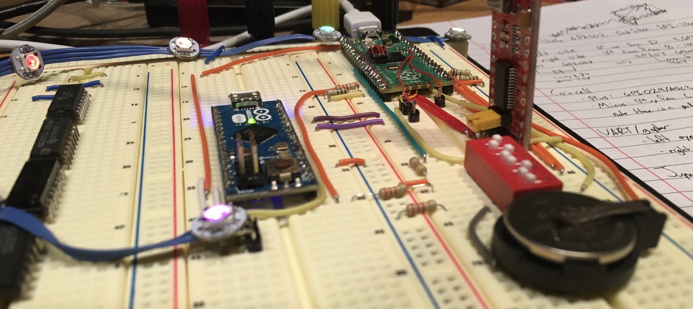
Ignore the Nixie tubes and random DIP ICs; I’m out of breadboards and needed someplace for them to hang out…
The UART adapter is for the two challenges that need it, and yes, it looks silly to have a whole Arduino Micro when I’m using three of its pins. This will get fixed at some point; probably when I move this to its own breadboard.
The DIP switch bank is only partially used:
| Switch | Purpose | Effect |
|---|---|---|
| 1 | Enables high-side resistor for thermistor emulation | Open to complete 🍶 |
| 2 | Connects GPIO12 and ADC1 |
Close to complete 🍟 |
| 3 | Connects GPIO11 and ADC0 |
Open to complete 🔪 |
| 6 | Enables low-side resistor for thermistor emulation | Open to complete 🍧 |
| 7 | Connects coin cell | Close to complete 🍘 |
APA102 Conversion Code
There are several janky things about this program, but probably the most egregious/clever hack is that I take the Blue-Green-Red data format of the APA102 data stream, feed it direcly to the Adafruit_NeoPixel library’s setPixelColor(uint16_t index, uint32_t color) function (which expects Red-Green-Blue ordering), and then fix it in post by setting the WS2812s’ neoPixelType to be NEO_GBR (Green-Blue-Red) - even through my WS2812s actually want NEO_GRB (Green-Red-Blue).
The trick there is that the positions of the red and blue bytes get swapped between the APA102 data stream and the setPixelColor value, so making the library swap them back neatly resolves that for me.
#include <Adafruit_NeoPixel.h>

// Connects to TP5 / GPIO25 on RP2040
#define CLK (1 << PB7)
// pin 11

// Connects to GPIO24 on RP2040 (removed R1, R10)
#define DAT (1 << PB5)
// pin 9

// 7 NeoPixels on pin 2
Adafruit_NeoPixel strip = Adafruit_NeoPixel(7, 2, NEO_GBR + NEO_KHZ800);
// APA102 data stream is                [I]BGR
// Adafruit_Neopixel.setPixelColor() is [W]RGB

// Physical WS2812s are GRB; we only need to swap red and green for APA102 --> Adafruit conversion
// So we lied to the constructor and said we have GBR instead of GRB, making Adafruit only do the byte-swapping once

void setup()
{
  DDRB &= ~(CLK | DAT);
  DDRC |= LED;

  strip.begin();
  strip.show();
}

// Yeah these are globals, sue me - I didn't want to make another while() loop inside loop()
uint32_t value = 0;
int clkCount = 0;
int index = 0;

void loop()
{
  while(!(PINB & CLK)); // CLK low

  value <<= 1;
  value |= ((PINB & DAT) != 0); // order matters here - want to have the current value in the LSB for later when we write it to the NeoPixel string

  ++clkCount; // yeah I'm one-indexing it since I want to do some modulo operations

  if ((clkCount % 8) == 0) // end of a byte
  {
    if (clkCount == 32) // check for valid start 32-bit set of 0's
    {
      if (value != 0)
      {
        index = 0;
        clkCount = 0;
      }
    }
    else // data starts after 32-bit start packet
    {
      if (clkCount <= 256) // 1-byte stop packet starts after 256 clocks (i.e. 1 start packet plus 7 data packets is 8 packets * 32 bits per packet = 256)
      {
          if (clkCount % 32 == 0) // packets are 32 bits long
          {
            PORTC |= LED;
            if ((value & 0x0ff000000) == 0x0ff000000) // skip glitches; pretty sure this is a timing issue rather than something janky on the 5n4ck3y/APA102 side
            {
              strip.setPixelColor(index, value); // The Adafruit library ignores the high byte (APA102 intensity, Adafruit W channel - except that's disabled)
            }
            ++index;
          }
      }
      else if (clkCount == 264) // end of stop packet (256 + 8)
      {
        clkCount = 0;
        index = 0;
        value = 0;
        strip.show();
      }
    }
  }

  while(PINB & CLK);
}